NW-MS6
SECTION 3
DISASSEMBLY
• This set can be disassembled in the order shown below.
3-1. DISASSEMBLY FLOW
Set ![]()
![]()
![]()
![]()
![]()
![]()
“Main board”
Note: Follow the disassembly procedure in the numerical order given.
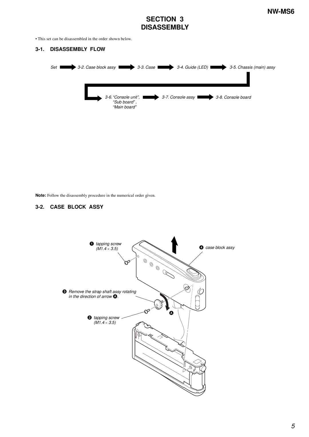
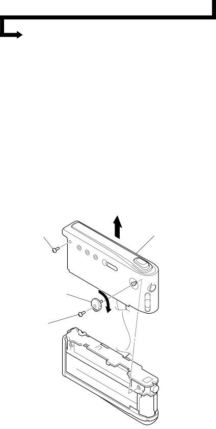
3-2. CASE BLOCK ASSY
1 tapping screw | 4 case block assy |
(M1.4 ⋅ 3.5) |
3 Remove the strap shaft assy rotating in the direction of arrow A.
A
2tapping screw
(M1.4 ⋅ 3.5)
5