For Machines Mfg. Since 8/09 | S E R V I C E | Model SB1020 |
220V Conversion
Wiring diagrams are provided in this section showing the Model SB1020 wired for both 110V and 220V. Refer to these diagrams if needed when following this procedure. Additionally, you must purchase a 220V switch in order to complete the conversion.
Items Needed | Qty. |
220V Switch (Part No. PSB1020204) | 1 |
Phillips Screwdriver #2 | 1 |
Wrench 18mm | 1 |
Wire Nut (sized for three 14 Ga. wires) | 1 |
Electrical Tape | As needed |
Wire Stripper | As needed |
To convert the Model SB1020 to 220V:
1.DISCONNECT BANDSAW FROM POWER!
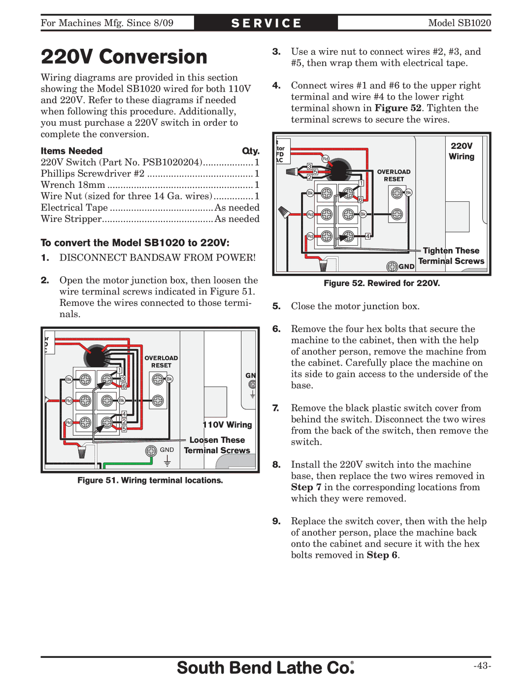
2.Open the motor junction box, then loosen the wire terminal screws indicated in Figure 51. Remove the wires connected to those termi- nals.
t |
|
|
itor |
|
|
FD |
|
|
AC |
|
|
| OVERLOAD |
|
1 | RESET |
|
| GND | |
| 3 | |
|
| |
| 6 |
|
| 4 |
|
| 2 | 110V Wiring |
| 5 | |
|
| |
|
| Loosen These |
| GND | Terminal Screws |
Figure 51. Wiring terminal locations.
3.Use a wire nut to connect wires #2, #3, and #5, then wrap them with electrical tape.
4.Connect wires #1 and #6 to the upper right terminal and wire #4 to the lower right terminal shown in Figure 52. Tighten the terminal screws to secure the wires.
art |
|
| 220V |
citor |
|
| |
MFD |
|
| Wiring |
VAC |
|
| |
|
|
| |
3 | 5 |
| OVERLOAD |
2 |
| 1 | RESET |
|
| G | |
|
|
| |
|
| 6 |
|
4 |
Tighten These |
GND Terminal Screws |
Figure 52. Rewired for 220V.
5.Close the motor junction box.
6.Remove the four hex bolts that secure the machine to the cabinet, then with the help of another person, remove the machine from the cabinet. Carefully place the machine on its side to gain access to the underside of the base.
7.Remove the black plastic switch cover from behind the switch. Disconnect the two wires from the back of the switch, then remove the switch.
8.Install the 220V switch into the machine base, then replace the two wires removed in Step 7 in the corresponding locations from which they were removed.
9.Replace the switch cover, then with the help of another person, place the machine back onto the cabinet and secure it with the hex bolts removed in Step 6.