For Product Mfg. Since 1/10 | P R E P A R A T I O N | Model SB1269 |
Installation
To install the taper attachment:
1. DISCONNECT LATHE FROM POWER!
2. With the assistance of a helper and using a 6mm hex wrench, remove the four cap screws holding the splash guard on the rear of the lathe.
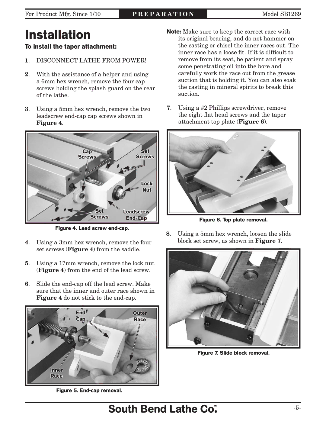
3. Using a 5mm hex wrench, remove the two leadscrew
Cap | Set |
Screws | Screws |
| Lock |
| Nut |
Set | Leadscrew |
Screws |
Figure 4. Lead screw end-cap.
4. Using a 3mm hex wrench, remove the four
set screws (Figure 4) from the saddle.
5. Using a 17mm wrench, remove the lock nut (Figure 4) from the end of the lead screw.
6. Slide the
End | Outer |
Cap | Race |
Inner
Race
Figure 5. End
 -cap
-cap removal.
Note: Make sure to keep the correct race with its original bearing, and do not hammer on the casting or chisel the inner races out. The inner race has a loose fit. If it is difficult to remove from its seat, be patient and spray some penetrating oil into the bore and carefully work the race out from the grease suction that is holding it. You can also soak the casting in mineral spirits to break this suction.
7. Using a #2 Phillips screwdriver, remove the eight flat head screws and the taper attachment top plate (Figure 6).
Figure 6.
 Top plate removal.
8. Using a 5mm hex wrench, loosen the slide block set screw, as shown in Figure 7.