28 | BIOS Setup |
Memory Hole At 15M- Choose Enabled or Disabled (default).
16MSome interface cards will map their ROM address to this area. If this occurs, you should select Enabled, otherwise use Disabled.
3.After you have finished with the Chipset Features Setup, press the <ESC> key and follow the screen instructions to save or disregard your settings.
Power Management Setup
The Power Management Setup option sets the systemÕs power saving functions.
Run the Power Management Setup as follows.
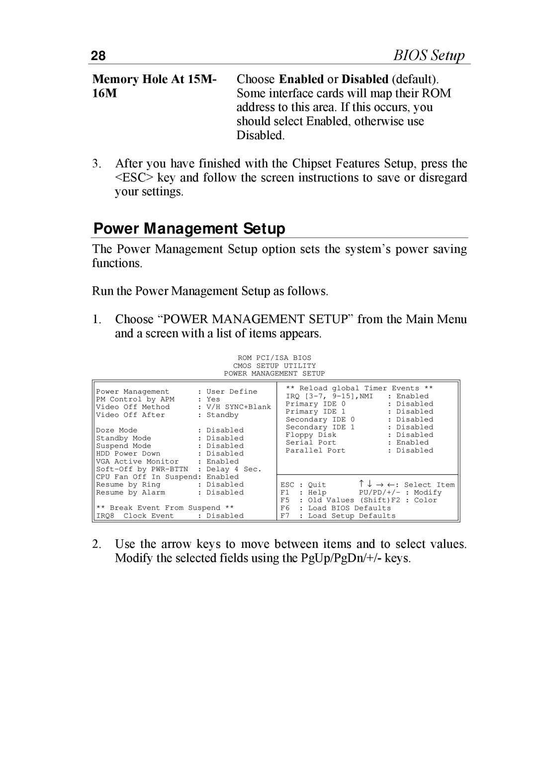
1.Choose ÒPOWER MANAGEMENT SETUPÓ from the Main Menu and a screen with a list of items appears.
ROM PCI/ISA BIOS
CMOS SETUP UTILITY
POWER MANAGEMENT SETUP
Power Management | : User Define | |
PM Control by APM | : Yes | |
Video Off | Method | : V/H SYNC+Blank |
Video Off | After | : Standby |
Doze Mode |
| : Disabled |
Standby Mode | : Disabled | |
Suspend Mode | : Disabled | |
HDD Power | Down | : Disabled |
VGA Active Monitor | : Enabled | |
: Delay 4 Sec. | ||
CPU Fan Off In Suspend: Enabled | ||
Resume by | Ring | : Disabled |
Resume by | Alarm | : Disabled |
** Break Event From Suspend ** | ||
IRQ8 Clock Event | : Disabled | |
** Reload global Timer Events **
IRQ | : Enabled |
Primary IDE 0 | : Disabled |
Primary IDE 1 | : Disabled |
Secondary IDE 0 | : Disabled |
Secondary IDE 1 | : Disabled |
Floppy Disk | : Disabled |
Serial Port | : Enabled |
Parallel Port | : Disabled |
ESC : Quit − ↓ → ←: Select Item
F1 : Help
F5 : Old Values (Shift)F2 : Color
F6 : Load BIOS Defaults
F7 : Load Setup Defaults
2.Use the arrow keys to move between items and to select values. Modify the selected fields using the PgUp/PgDn/+/- keys.