The dome camera must be installed by qualified service personnel in accordance with all local and federal electrical and building codes. The system should be installed according to Figures 4 through 9.
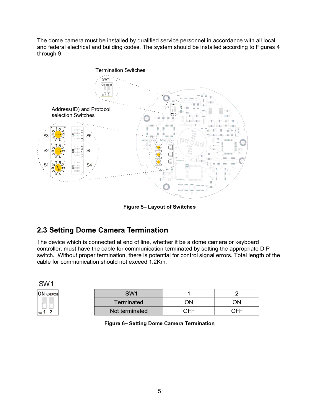
Termination Switches
SW1
ON KSD02H
9A 1 2
Address(ID) and Protocol selection Switches
![]()
![]() S3
S3
S2
S1
6 | 7 |
| |
5 |
|
4 | |
| 3 |
6 | 7 |
| |
5 |
|
4 | |
| 3 |
6 | 7 |
| |
5 |
|
4 | |
| 3 |
| |
8 | 8 |
9 | |
| 0 |
2 | 1 |
1 | |
8 | 8 |
9 | |
| 0 |
2 | 1 |
1 | |
8 | 8 |
9 | |
| 0 |
2 | 1 |
1 | |
on | 2 3 4 |
| 1 |
on | 2 3 4 |
| 1 |
on |
|
S6
S5
S4 ![]()
![]()
56 | 789 | ||
| 0 | ||
4 | 2 | 1 | |
| 3 |
| |
56 | 789 | ||
| 0 | ||
4 | 2 | 1 | |
| 3 |
| |
56 | 789 | ||
| 0 | ||
4 | 2 | 1 | |
| 3 |
| |
Figure 5– Layout of Switches
2.3 Setting Dome Camera Termination
The device which is connected at end of line, whether it be a dome camera or keyboard controller, must have the cable for communication terminated by setting the appropriate DIP switch. Without proper termination, there is potential for control signal errors. Total length of the cable for communication should not exceed 1.2Km.
SW1
ON KSD02H |
| SW1 | 1 | 2 | ||||
|
|
|
|
|
| Terminated | ON | ON |
|
|
|
|
|
| |||
|
|
|
|
|
| Not terminated | OFF | OFF |
9A 1 2 |
| |||||||
|
|
|
|
|
|
|
|
|
Figure 6– Setting Dome Camera Termination
5