3.Interface specifications
3.1 Parallel interface (Centronics)
1) Data input | : 8 bit parallel method(DATA 0 – DATA 7) |
|
|
| ||||
2) Control signals | : /ACK, BUSY, /STB, /ERROR, PE, SLCT, /INIT |
|
| |||||
3) Input signal to a printer |
|
|
|
|
|
| ||
DATA 0 – 7 | : 8 bit parallel signal(positive logic) |
|
|
| ||||
/STB | : Signal to read 8 bit data(negative logic) |
|
|
| ||||
/INIT | : Signal to reset an entire printer(negative logic) |
|
| |||||
/LF | : Signal to feed paper to print mechanism(negative logic) | |||||||
4) Output signal from a printer |
|
|
|
|
|
| ||
/ACK | : Enquiry signal for 8 bit data. It’s also pulse signal which is output after | |||||||
|
| BUSY signals (negative logic) |
|
|
|
| ||
BUSY | : Indicate BUSY status of the printer. Inputs new data at LOW status | |||||||
|
| (positive logic) |
|
|
|
|
| |
/ERROR | : This signal becomes LOW when a printer is in the alarm status. | |||||||
In the LOW status, all control circuits in the printer stops (negative logic) | ||||||||
PE | : Outputs when roll paper becomes empty (positive logic) | |||||||
SLCT | : Signal to indicate |
|
| |||||
5) Input/Output signal level |
|
|
|
|
|
| ||
|
|
| Code | Standard value | Unit |
| ||
|
|
| Min. | TYP. | Max. |
| ||
|
|
|
|
|
| |||
| Input low level | VIL | - | - | 0.18Vcc | V |
| |
| Input high level | VIH | 0.7Vcc | - | - | V |
| |
| Output low level | VOL | - | - | 0.7Vcc | V |
| |
| Output high level | VOH | 0.7Vcc | - | - | V |
| |
*IOL4mA |
|
|
|
|
|
|
| |
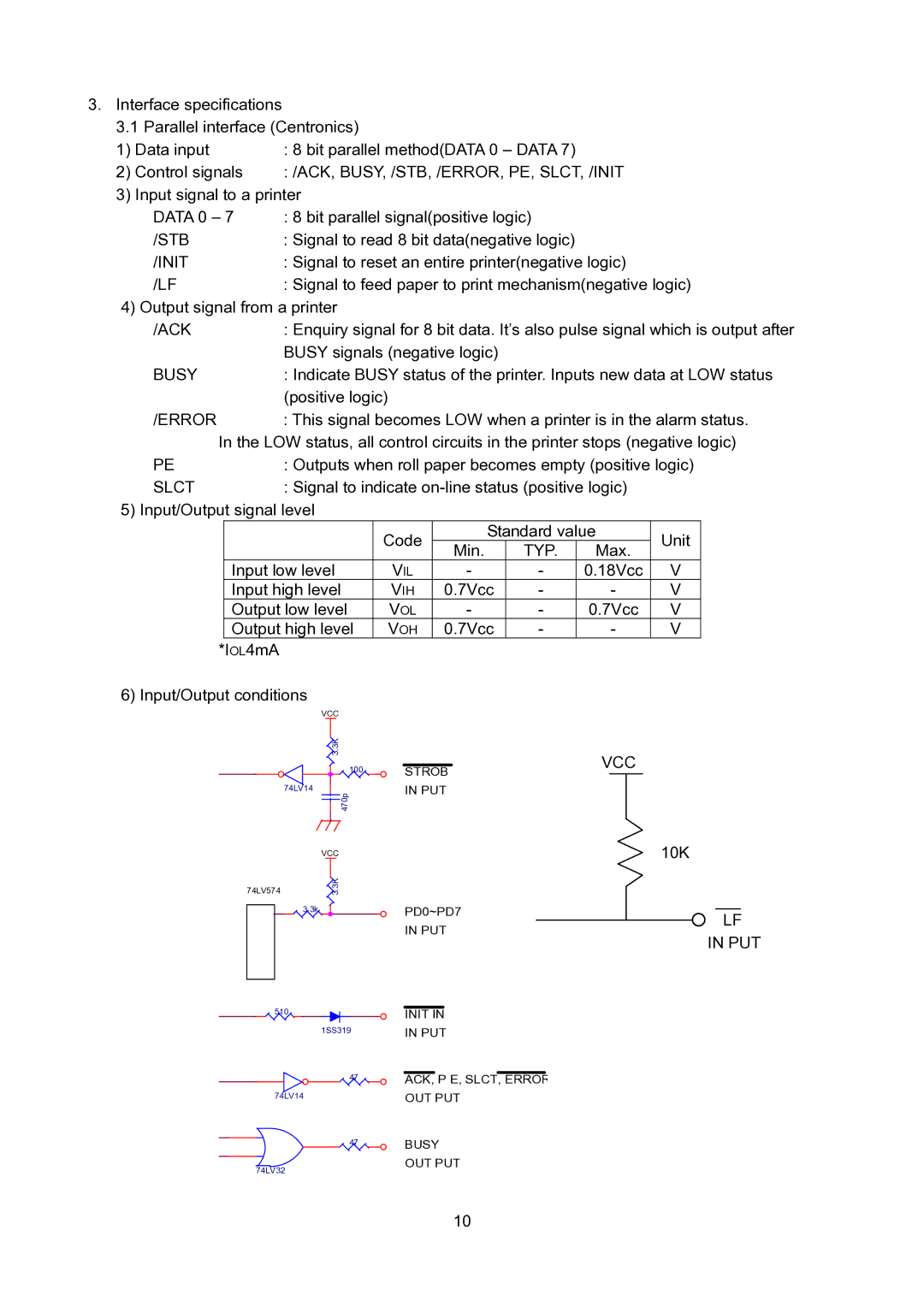
6) Input/Output conditions
74LV574
VCC
3.3K
100
74LV14
470p
VCC
3.3K
STROB IN PUT
VCC
10K
3.3k | PD0~PD7 |
| IN PUT |
510 | INIT IN |
1SS319 | IN PUT |
47 | ACK, P E, SLCT, ERROR |
74LV14 | OUT PUT |
47 | BUSY |
74LV32 | OUT PUT |
|
○LF IN PUT
10