4.Functions
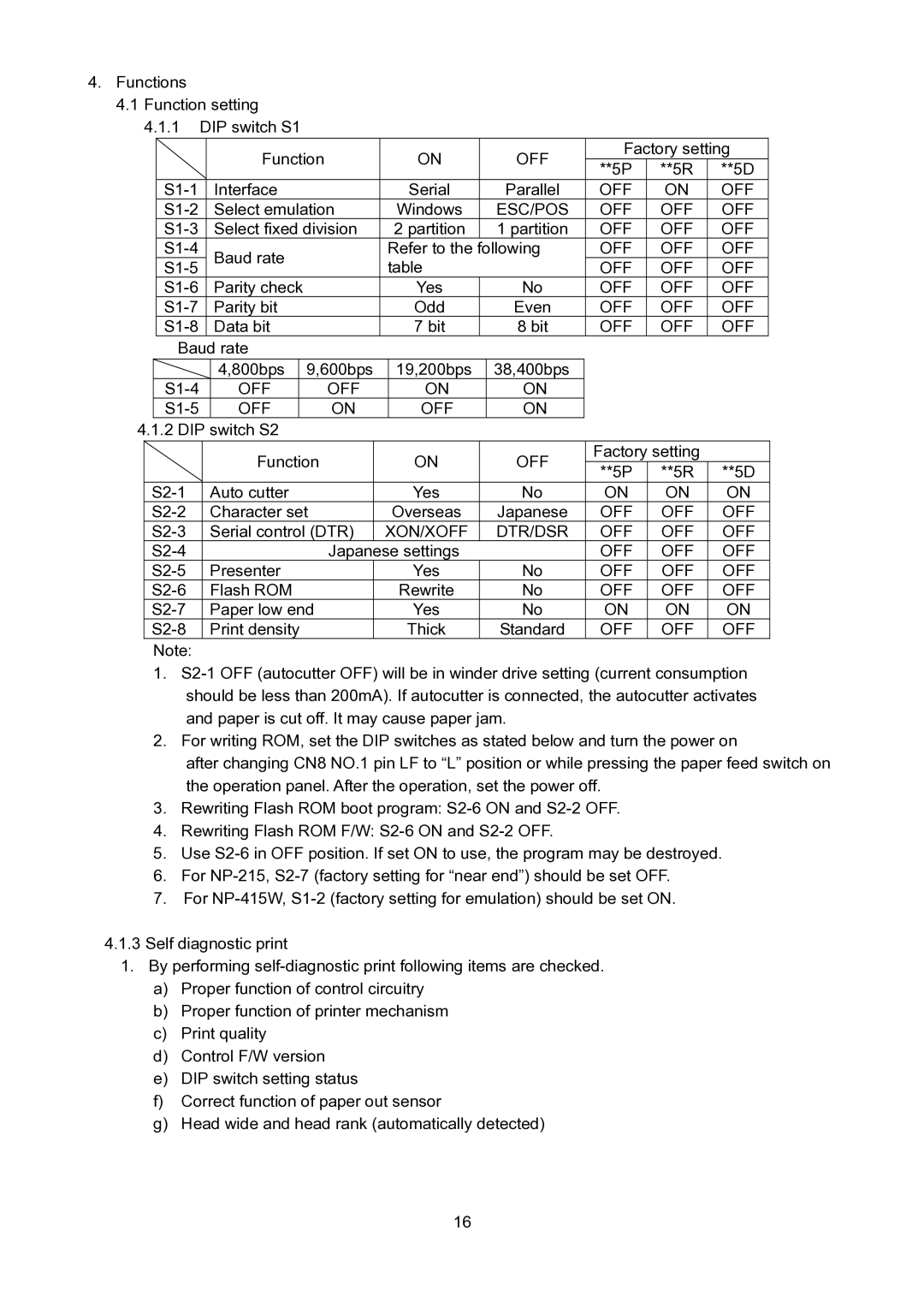
4.1 Function setting 4.1.1 DIP switch S1
|
|
|
|
| Function |
| ON |
| OFF | Factory setting | |||||
|
|
|
|
|
|
| **5P | **5R | **5D | ||||||
|
|
|
|
|
|
|
|
|
|
|
|
| |||
|
|
| Interface |
|
|
| Serial |
| Parallel | OFF | ON | OFF | |||
|
|
| Select emulation |
| Windows |
| ESC/POS | OFF | OFF | OFF | |||||
|
|
| Select fixed division |
| 2 partition |
| 1 partition | OFF | OFF | OFF | |||||
|
|
| Baud rate |
|
| Refer to the | following | OFF | OFF | OFF | |||||
|
|
|
| OFF | OFF | OFF | |||||||||
|
|
|
|
|
|
| table |
|
| ||||||
|
|
| Parity check |
|
|
| Yes |
| No | OFF | OFF | OFF | |||
|
|
| Parity bit |
|
|
| Odd |
| Even | OFF | OFF | OFF | |||
|
|
| Data bit |
|
|
| 7 bit |
| 8 bit | OFF | OFF | OFF | |||
|
| Baud rate |
|
|
|
|
|
|
|
|
| ||||
|
|
|
|
| 4,800bps |
| 9,600bps |
| 19,200bps |
| 38,400bps |
|
|
| |
|
|
| OFF |
| OFF |
| ON |
| ON |
|
|
| |||
|
|
| OFF |
| ON |
| OFF |
| ON |
|
|
| |||
4.1.2 DIP switch S2 |
|
|
|
|
|
|
|
|
| ||||||
|
|
|
|
| Function |
|
| ON |
| OFF | Factory setting |
| |||
|
|
|
|
|
|
|
| **5P | **5R | **5D | |||||
|
|
|
|
|
|
|
|
|
|
|
|
| |||
|
| Auto cutter |
|
|
| Yes |
| No | ON | ON | ON | ||||
|
| Character set |
|
| Overseas |
| Japanese | OFF | OFF | OFF | |||||
|
| Serial control (DTR) |
| XON/XOFF |
| DTR/DSR | OFF | OFF | OFF | ||||||
|
|
|
|
| Japanese settings |
|
| OFF | OFF | OFF | |||||
|
| Presenter |
|
|
| Yes |
| No | OFF | OFF | OFF | ||||
|
| Flash ROM |
|
|
| Rewrite |
| No | OFF | OFF | OFF | ||||
|
| Paper low end |
|
| Yes |
| No | ON | ON | ON | |||||
|
| Print density |
|
|
| Thick |
| Standard | OFF | OFF | OFF | ||||
|
| Note: |
|
|
|
|
|
|
|
|
|
|
|
| |
1.
2.For writing ROM, set the DIP switches as stated below and turn the power on
after changing CN8 NO.1 pin LF to “L” position or while pressing the paper feed switch on the operation panel. After the operation, set the power off.
3.Rewriting Flash ROM boot program:
4.Rewriting Flash ROM F/W:
5.Use
6.For
7.For
4.1.3Self diagnostic print
1.By performing
a)Proper function of control circuitry
b)Proper function of printer mechanism
c)Print quality
d)Control F/W version
e)DIP switch setting status
f)Correct function of paper out sensor
g)Head wide and head rank (automatically detected)
16