Installation Considerations
Rough In Dimensions
70°
20°
S
GA
35° |
| 1 1/4” SUPPLY GAS | 4” PVC |
| INTAKE AIR | ||
|
| CONNECTION | CONNECTION |
VENT |
|
| |
4 | INCH |
|
|
PVC | BACK | 69” | |
|
| (175.3 cm) | |
FRONT | T & P |
|
|
|
|
|
|
|
| 69” |
|
|
|
|
|
|
| (175.3 cm) |
|
| INTAKE AIR |
|
|
|
|
|
|
| 4 INCH PVC |
|
|
| TOP |
|
|
|
|
|
|
|
| |
|
| *1 1/2” NPT |
|
|
|
|
|
|
| WATER |
|
| T | E |
|
|
| OUTLET |
|
| & | V |
|
|
|
|
| PA |
| ||
|
|
|
|
|
| L |
|
|
|
| VALVE |
|
| V |
|
| OUT | FRONT |
|
|
| ||
EAN | DRAIN |
|
|
|
|
| |
CL |
|
|
|
|
|
| |
|
|
|
|
|
| 12” | |
|
|
|
| 18° |
| 45° | |
|
|
|
|
| (30.5 cm) | ||
45°
4” PVC
VENT CONNECTION
(exhaust elbow)
CONDENSATE
DRAIN CONNECTION
1/2 INCH PVC
WATER OUTLET HEIGHT
63INCHES (160 cm)
33.12” (84.1 cm)
OUTSIDE
DIAMETER
CLEANOUT
3/4” NPT
DRAIN
1 1/2” NPT
WATER INLET
75.50”
(191.8 cm)
50.77”
(129 cm)
4.86”
(12.34 cm)
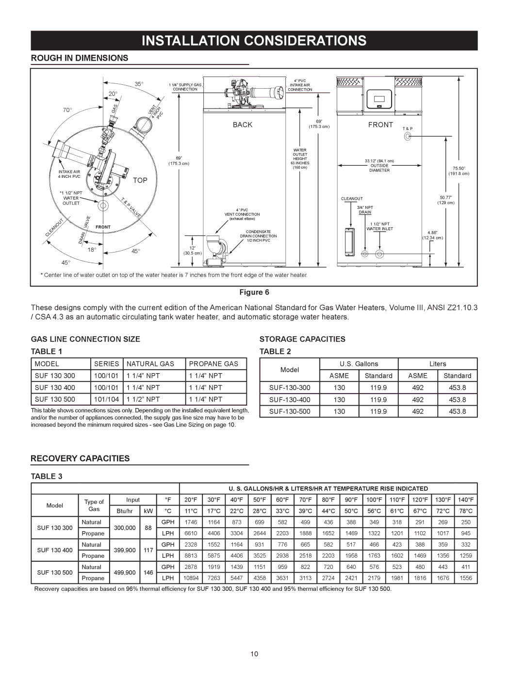
* Center line of water outlet on top of the water heater is 7 inches from the front edge of the water heater.
Figure 6
These designs comply with the current edition of the American National Standard for Gas Water Heaters, Volume III, ANSI Z21.10.3 / CSA 4.3 as an automatic circulating tank water heater, and automatic storage water heaters.
Gas Line Connection Size
Table 1
MODEL | SERIES | NATURAL GAS | PROPANE GAS |
SUF 130 300 | 100/101 | 1 1/4” NPT | 1 1/4” NPT |
SUF 130 400 | 100/101 | 1 1/4” NPT | 1 1/4” NPT |
SUF 130 500 | 101/104 | 1 1/2” NPT | 1 1/4” NPT |
This table shows connections sizes only. Depending on the installed equivalent length, and/or the number of appliances connected, the supply gas line size may have to be increased beyond the minimum required sizes - see Gas Line Sizing on page 10.
Storage Capacities
Table 2
Model | U.S. Gallons |
| Liters | ||
ASME | Standard | ASME |
| Standard | |
|
| ||||
130 | 119.9 | 492 |
| 453.8 | |
130 | 119.9 | 492 |
| 453.8 | |
130 | 119.9 | 492 |
| 453.8 | |
Recovery Capacities
Table 3
|
|
|
|
|
|
| U. S. Gallons/Hr & Liters/Hr at Temperature Rise Indicated |
|
| |||||||||
Model | Type of | Input |
| °F | 20°F | 30°F | 40°F | 50°F | 60°F | 70°F | 80°F | 90°F | 100°F | 110°F | 120°F | 130°F | 140°F | |
Gas | Btu/hr | kW | °C | 11°C | 17°C | 22°C | 28°C | 33°C | 39°C | 44°C | 50°C | 56°C | 61°C | 67°C | 72°C | 78°C | ||
| ||||||||||||||||||
|
| |||||||||||||||||
|
|
|
|
|
|
|
|
|
|
|
|
|
|
|
|
|
| |
SUF 130 300 | Natural | 300,000 | 88 | GPH | 1746 | 1164 | 873 | 699 | 582 | 499 | 436 | 388 | 349 | 318 | 291 | 269 | 250 | |
Propane | LPH | 6610 | 4406 | 3304 | 2644 | 2203 | 1888 | 1652 | 1469 | 1322 | 1201 | 1102 | 1017 | 945 | ||||
|
|
| ||||||||||||||||
|
|
|
|
|
|
|
|
|
|
|
|
|
|
|
|
|
| |
SUF 130 400 | Natural | 399,900 | 117 | GPH | 2328 | 1552 | 1164 | 931 | 776 | 665 | 582 | 517 | 466 | 423 | 388 | 359 | 332 | |
Propane | LPH | 8813 | 5875 | 4406 | 3525 | 2938 | 2518 | 2203 | 1958 | 1763 | 1602 | 1469 | 1356 | 1259 | ||||
|
|
| ||||||||||||||||
|
|
|
|
|
|
|
|
|
|
|
|
|
|
|
|
|
| |
SUF 130 500 | Natural | 499,900 | 146 | GPH | 2878 | 1919 | 1439 | 1151 | 959 | 822 | 720 | 640 | 576 | 523 | 480 | 443 | 411 | |
Propane | LPH | 10894 | 7263 | 5447 | 4358 | 3631 | 3113 | 2724 | 2421 | 2179 | 1981 | 1816 | 1676 | 1556 | ||||
|
|
| ||||||||||||||||
|
|
|
|
|
|
|
|
|
|
|
|
|
|
|
|
|
| |
Recovery capacities are based on 96% thermal efficiency for SUF 130 300, SUF 130 400 and 95% thermal efficiency for SUF 130 500.
10