Sequence Of Operation Flow Chart
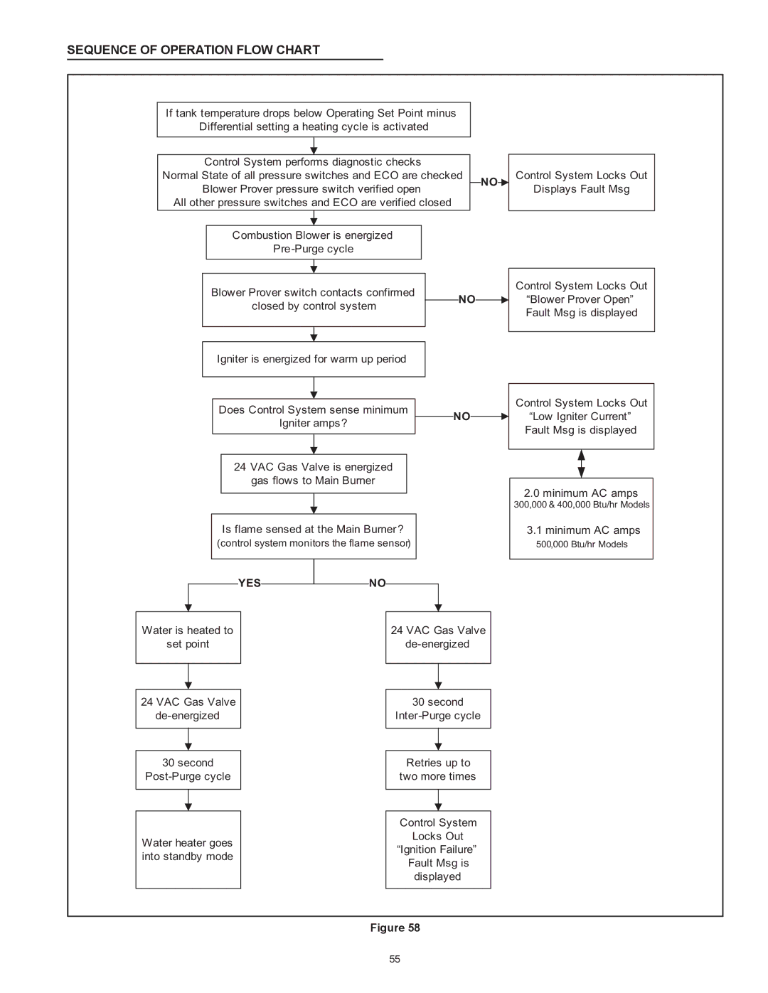
If tank temperature drops below Operating Set Point minus
Differential setting a heating cycle is activated
| Control System performs diagnostic checks |
|
|
|
|
|
| Control System Locks Out | ||||
Normal State of all pressure switches and ECO are checked |
|
|
|
|
| |||||||
| NO |
|
| |||||||||
| Blower Prover pressure switch verified open |
|
|
|
|
| Displays Fault Msg | |||||
|
|
|
|
|
|
| ||||||
All other pressure switches and ECO are verified closed |
|
|
|
|
|
|
| |||||
|
|
|
|
|
|
|
|
|
|
| ||
|
|
|
|
|
|
|
|
|
|
|
|
|
|
| Combustion Blower is energized |
|
|
|
|
|
|
|
|
| |
|
|
|
|
|
|
|
|
|
|
| ||
|
|
|
|
|
|
|
|
|
|
|
|
|
|
|
|
|
|
|
|
|
|
|
|
|
|
|
|
|
|
|
|
|
|
|
|
|
| Control System Locks Out |
|
| Blower Prover switch contacts confirmed |
|
|
|
|
|
|
| |||
|
|
| NO |
|
|
|
| “Blower Prover Open” | ||||
|
| closed by control system |
|
|
|
|
| |||||
|
|
|
|
|
|
|
|
| Fault Msg is displayed | |||
|
|
|
|
|
|
|
|
|
|
|
| |
|
|
|
|
|
|
|
|
|
|
|
|
|
|
|
|
|
|
|
|
|
|
|
|
|
|
|
| Igniter is energized for warm up period |
|
|
|
|
|
|
|
| ||
|
|
|
|
|
|
|
|
|
|
|
|
|
|
|
|
|
|
|
|
|
|
|
|
|
|
Does Control System sense minimum |
|
| |
| NO | ||
Igniter amps? |
| ||
|
| ||
|
|
|
|
|
|
|
|
24 VAC Gas Valve is energized
gas flows to Main Burner
Is flame sensed at the Main Burner?
(control system monitors the flame sensor)
YES NO
NO
Water is heated to |
| 24 VAC Gas Valve | ||
set point |
| |||
|
|
|
|
|
|
|
|
|
|
Control System Locks Out “Low Igniter Current” Fault Msg is displayed
2.0 minimum AC amps
300,000 & 400,000 Btu/hr Models
3.1 minimum AC amps
500,000 Btu/hr Models
24 VAC Gas Valve
30second
Water heater goes into standby mode
30second
Retries up to two more times
Control System
Locks Out
“Ignition Failure”
Fault Msg is
displayed
Figure 58
55