Features And Components
Basic Operation
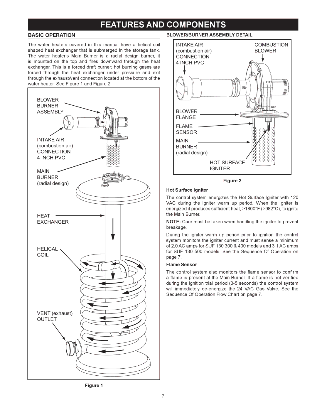
The water heaters covered in this manual have a helical coil shaped heat exchanger that is submerged in the storage tank. The water heater’s Main Burner is a radial design burner, it is mounted on the top and fires downward through the heat exchanger. This is a forced draft burner; hot burning gases are forced through the heat exchanger under pressure and exit through the exhaust/vent connection located at the bottom of the water heater. See Figure 1 and Figure 2.
BLOWER |
BURNER |
ASSEMBLY |
INTAKE AIR |
(combustion air) |
CONNECTION |
4 INCH PVC |
MAIN |
BURNER |
(radial design) |
HEAT |
EXCHANGER |
HELICAL |
COIL |
VENT (exhaust) |
OUTLET |
Figure 1
Blower/Burner Assembly Detail
INTAKE AIR | COMBUSTION |
(combustion air) | BLOWER |
CONNECTION |
|
4 INCH PVC |
|
BLOWER |
|
FLANGE |
|
FLAME |
|
SENSOR |
|
MAIN |
|
BURNER |
|
(radial design) |
|
HOT SURFACE |
|
IGNITER |
|
Figure 2
Hot Surface Igniter
The control system energizes the Hot Surface Igniter with 120 VAC during the igniter warm up period. When the igniter is energized it produces sufficient heat, >1800°F (>982°C), to ignite the Main Burner.
Note: Care must be taken when handling the igniter to prevent breakage.
During the igniter warm up period prior to ignition the control system monitors the igniter current and must sense a minimum of 2.0 AC amps for SUF 130 300 & 400 models and 3.1 AC amps for SUF 130 500 models. See the Sequence Of Operation on page 7.
Flame Sensor
The control system also monitors the flame sensor to confirm a flame is present at the Main Burner. If a flame is not verified during the ignition trial period
7