Chapter 6: Troubleshooting
6-1 Introduction
The utmost in safety precautions should be observed at all times when working on or around the machine and the electrical components. All normal
The use of good quality test equipment cannot be
Before making haphazard substitutions and repairs when defective electrical components are malfunctioning, we recommend that you check the associated circuitry and assemblies for other defective devices. It is common to replace the obviously damaged component without actually locating the real cause of the trouble. Such hasty substitutions will only destroy the new component. Refer to wiring diagrams and schematics.
Locating mechanical problems, should they occur, is relatively straightforward. When necessary, refer to the parts catalog section.
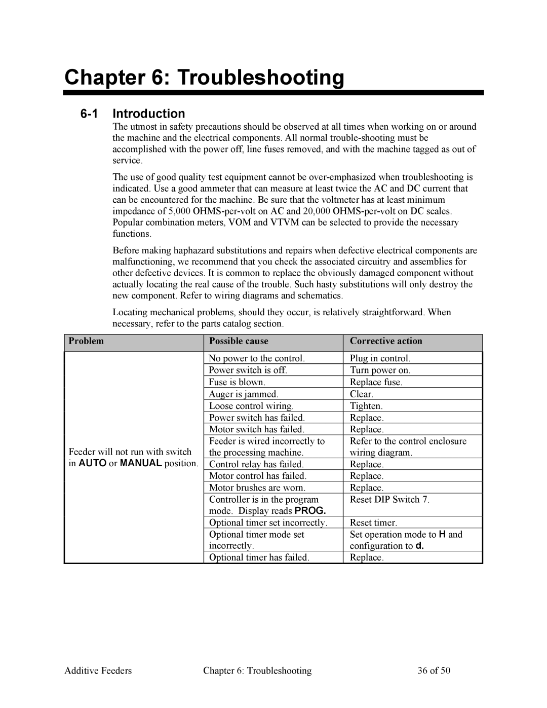
Problem | Possible cause | Corrective action |
|
|
|
| No power to the control. | Plug in control. |
| Power switch is off. | Turn power on. |
| Fuse is blown. | Replace fuse. |
| Auger is jammed. | Clear. |
| Loose control wiring. | Tighten. |
| Power switch has failed. | Replace. |
| Motor switch has failed. | Replace. |
Feeder will not run with switch | Feeder is wired incorrectly to | Refer to the control enclosure |
the processing machine. | wiring diagram. | |
in AUTO or MANUAL position. | Control relay has failed. | Replace. |
| Motor control has failed. | Replace. |
| Motor brushes are worn. | Replace. |
| Controller is in the program | Reset DIP Switch 7. |
| mode. Display reads PROG. |
|
| Optional timer set incorrectly. | Reset timer. |
| Optional timer mode set | Set operation mode to H and |
| incorrectly. | configuration to d. |
| Optional timer has failed. | Replace. |
Additive Feeders | Chapter 6: Troubleshooting | 36 of 50 |