INSTALLATION INSTRUCTIONS
INSTALLATION
IMPORTANT:ENSURE THAT THE APPLIANCE IS CORRECTLY ADJUSTED FOR THE GAS TYPE AND CATEGORY APPLICABLE IN THE COUNTRY OF USE. REFER TO DATABADGE AND TECHNICAL SPECIFICATIONS AT THE FRONT OF THE BOOKLET.
FOR DETAILS OF CHANGING BETWEEN GAS TYPES REFER TO SERVICING SECTION 9.
1.SAFETY PRECAUTIONS
1.1This appliance must be installed in accordance with the rules in force, and used only in a sufficiently ventilated space. Please read these instructions before installation and use of this appliance.
1.2These instructions must be left intact with the user.
1.3Do not attempt to burn rubbish on this appliance.
1.4In your own interest, and those of safety, this appliance must be installed by competent persons in accordance with local and national codes of practice. Failure to install the appliance correctly could lead to prosecution.
1.5Keep all plastic bags away from young children.
2.UNPACKING
2.1Remove the appliance from its packaging, and check that it is complete and undamaged.
2.2Put the loose ceramic parts to one side so that they are not damaged during installation.
3.INSTALLATION
These fires have preset High and Low settings with a Gas working pressure as listed below.
20mb on Natural Gas, 29mb on Butane and 37mb on Propane with the fire on full.
3.1Ensure the minimum opening dimensions are correct, place the decorative basket in the opening ensuring that is sits centrally.
3.2Place the gas fire unit centrally into the decorative basket and mark the fixing positions through the holes in the tray feet.
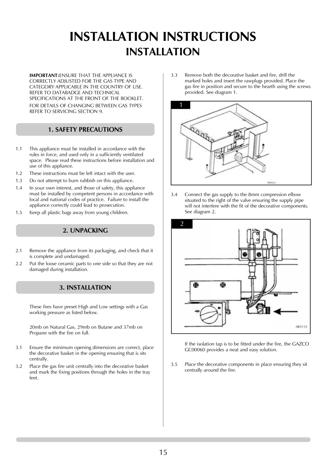
3.3Remove both the decorative basket and fire, drill the marked holes and insert the rawplugs provided. Place the gas fire in position and secure to the hearth using the screws provided. See diagram 1.
1
3.4Connect the gas supply to the 8mm compression elbow situated to the right of the valve ensuring the supply pipe will not interfere with the fit of the decorative components. See diagram 2.
2
If the isolation tap is to be fitted under the fire, the GAZCO GC00060 provides a neat and easy solution.
3.5Place the decorative components in place ensuring they sit centrally around the fire.
15