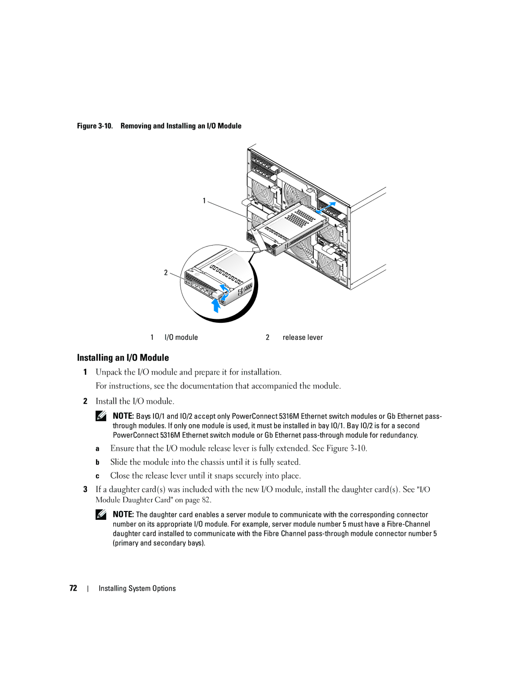
Figure 3-10. Removing and Installing an I/O Module
1
2
1 I/O module | 2 | release lever |
Installing an I/O Module
1Unpack the I/O module and prepare it for installation.
For instructions, see the documentation that accompanied the module.
2Install the I/O module.
NOTE: Bays IO/1 and IO/2 accept only PowerConnect 5316M Ethernet switch modules or Gb Ethernet pass- through modules. If only one module is used, it must be installed in bay IO/1. Bay IO/2 is for a second PowerConnect 5316M Ethernet switch module or Gb Ethernet
aEnsure that the I/O module release lever is fully extended. See Figure
bSlide the module into the chassis until it is fully seated.
cClose the release lever until it snaps securely into place.
3If a daughter card(s) was included with the new I/O module, install the daughter card(s). See "I/O Module Daughter Card" on page 82.
NOTE: The daughter card enables a server module to communicate with the corresponding connector number on its appropriate I/O module. For example, server module number 5 must have a
72
