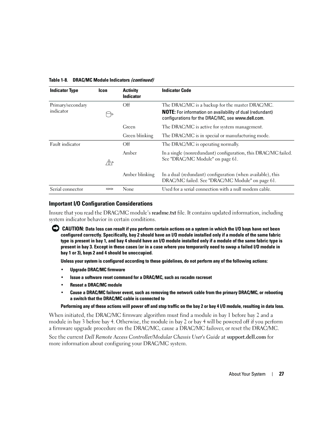
Table
Indicator Type | Icon | Activity | Indicator Code |
|
| Indicator |
|
|
|
|
|
Primary/secondary |
| Off | The DRAC/MC is a backup for the master DRAC/MC. |
indicator |
|
| NOTE: For information on availability of dual (redundant) |
|
|
| configurations for the DRAC/MC, see www.dell.com. |
|
| Green | The DRAC/MC is active for system management. |
|
| Green blinking | The DRAC/MC is in special or manufacturing mode. |
|
|
|
|
Fault indicator |
| Off | The DRAC/MC is operating normally. |
|
| Amber | In a single (nonredundant) configuration, this DRAC/MC failed. |
|
|
| See "DRAC/MC Module" on page 61. |
|
| Amber blinking | In a dual (redundant) configuration (when available), this |
|
|
| DRAC/MC failed. See "DRAC/MC Module" on page 61. |
|
|
|
|
Serial connector |
| None | Used for a serial connection with a null modem cable. |
|
|
|
|
Important I/O Configuration Considerations
Insure that you read the DRAC/MC module’s readme.txt file. It contains updated information, including system indicator behavior in certain conditions.
![]() CAUTION: Data loss can result if you perform certain actions on a system in which the I/O bays have not been configured correctly. Specifically, bay 2 should have an I/O module installed only if a module of the same fabric type is present in bay 1, and bay 4 should have an I/O module installed only if a module of the same fabric type is present in bay 3. Except in these cases (or in a case where you temporarily need to swap a failed I/O module in bay 1 or 3), bays 2 and 4 should be unoccupied.
CAUTION: Data loss can result if you perform certain actions on a system in which the I/O bays have not been configured correctly. Specifically, bay 2 should have an I/O module installed only if a module of the same fabric type is present in bay 1, and bay 4 should have an I/O module installed only if a module of the same fabric type is present in bay 3. Except in these cases (or in a case where you temporarily need to swap a failed I/O module in bay 1 or 3), bays 2 and 4 should be unoccupied.
Unless your system is configured according to these guidelines, do not perform any of the following actions:
•Upgrade DRAC/MC firmware
•Issue a software reset command for a DRAC/MC, such as racadm racreset
•Reseat a DRAC/MC module
•Cause a DRAC/MC failover event, such as removing the network cable from the primary DRAC/MC, or rebooting a switch that the DRAC/MC cable is connected to
Performing any of these actions will power off and stop traffic on the bay 2 or bay 4 I/O module, resulting in data loss.
When initiated, the DRAC/MC firmware algorithm must find a module in bay 1 before bay 2 and a module in bay 3 before bay 4. Otherwise, the module in bay 2 or bay 4 will be powered off if you perform a firmware upgrade procedure on the DRAC/MC, cause a DRAC/MC failover, or reset the DRAC/MC.
See the current Dell Remote Access Controller/Modular Chassis User's Guide at support.dell.com for more information about configuring your DRAC/MC system.
About Your System
27
