10 About Your System
System Overview
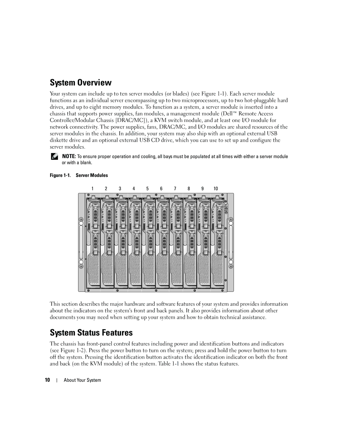
Your system can include up to ten server modules (or blades) (see Figure1-1). Each server module
functions as an individual server encompassing up to two microprocessors, up to two hot-pluggable hard
drives, and up to eight memory modules. To function as a system, a server module is inserted into a
chassis that supports power supplies, fan modules, a management module (Dell
Remote Access
Controller/Modular Chassis [DRAC/MC]), a KVM switch module, and at least one I/O module for
network connectivity. The power supplies, fans, DRAC/MC, and I/O modules are shared resources of the
server modules in the chassis. In addition, your system may also ship with an optional external USB
diskette drive and an optional external USB CD drive, which you can use to set up and configure the
server modules.
NOTE: To ensure proper operation and cooling, all bays must be populated at all times with either a server module
or with a blank.
Figure 1-1. Server Modules
This section describes the major hardware and software features of your system and provides information
about the indicators on the system's front and back panels. It also provides information about other
documents you may need when setting up your system and how to obtain technical assistance.
System Status Features
The chassis has front-panel control features including power and identification buttons and indicators
(see Figure1-2). Press the power button to turn on the system; press and hold the power button to turn
off the system. Pressing the identification button activates the identification indicator on both the front
and back (on the KVM module) of the system. Table1-1 shows the status features.
123456 78910