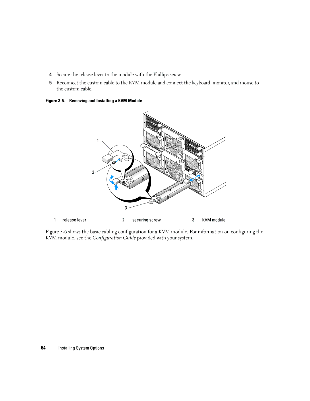
4Secure the release lever to the module with the Phillips screw.
5Reconnect the custom cable to the KVM module and connect the keyboard, monitor, and mouse to the custom cable.
Figure 3-5. Removing and Installing a KVM Module
1
2 ![]()
3 |
1 release lever | 2 | securing screw | 3 | KVM module |
Figure 3-6 shows the basic cabling configuration for a KVM module. For information on configuring the KVM module, see the Configuration Guide provided with your system.
64
