Inside the Server Module
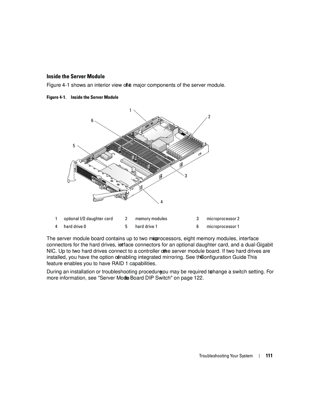
Figure 4-1 shows an interior view of the major components of the server module.
Figure 4-1. Inside the Server Module
1
2
6 ![]()
5
![]() 3
3
|
|
| 4 |
|
|
1 | optional I/O daughter card | 2 | memory modules | 3 | microprocessor 2 |
4 | hard drive 0 | 5 | hard drive 1 | 6 | microprocessor 1 |
The server module board contains up to two microprocessors, eight memory modules, interface connectors for the hard drives, interface connectors for an optional daughter card, and a
During an installation or troubleshooting procedure, you may be required to change a switch setting. For more information, see "Server Module Board DIP Switch" on page 122.
Troubleshooting Your System