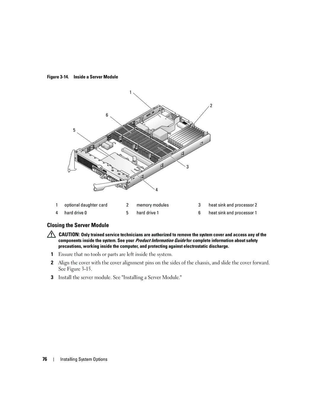
Figure 3-14. Inside a Server Module
1
2
6 ![]()
5
|
|
|
| 3 |
|
|
|
| 4 |
|
|
1 | optional daughter card | 2 | memory modules | 3 | heat sink and processor 2 |
4 | hard drive 0 | 5 | hard drive 1 | 6 | heat sink and processor 1 |
Closing the Server Module
CAUTION: Only trained service technicians are authorized to remove the system cover and access any of the components inside the system. See your Product Information Guide for complete information about safety precautions, working inside the computer, and protecting against electrostatic discharge.
1Ensure that no tools or parts are left inside the system.
2Align the cover with the cover alignment pins on the sides of the chassis, and slide the cover forward. See Figure
3Install the server module. See "Installing a Server Module."
76
