6Remove the KVM module. See "Removing a KVM Module" on page 63.
7Remove the I/O modules. See "Removing an I/O Module" on page 71.
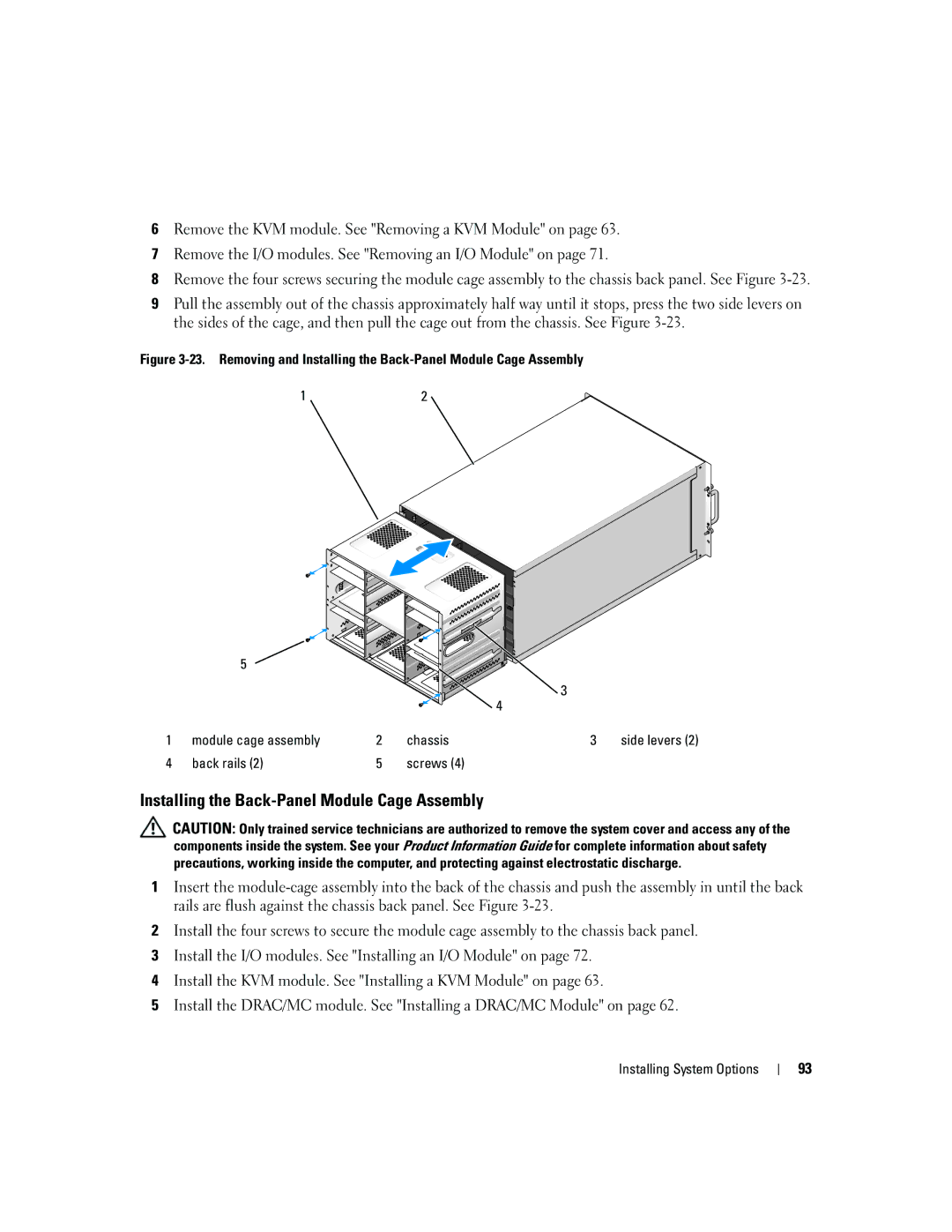
8Remove the four screws securing the module cage assembly to the chassis back panel. See Figure
9Pull the assembly out of the chassis approximately half way until it stops, press the two side levers on the sides of the cage, and then pull the cage out from the chassis. See Figure
Figure 3-23. Removing and Installing the Back-Panel Module Cage Assembly
1 | 2 |
| 5 |
|
|
|
|
|
|
|
|
|
| 3 |
|
|
|
|
|
| 4 |
|
1 | module cage assembly | 2 | chassis | 3 | side levers (2) | |
4 | back rails | (2) | 5 | screws (4) |
|
|
Installing the Back-Panel Module Cage Assembly
![]() CAUTION: Only trained service technicians are authorized to remove the system cover and access any of the components inside the system. See your Product Information Guide for complete information about safety precautions, working inside the computer, and protecting against electrostatic discharge.
CAUTION: Only trained service technicians are authorized to remove the system cover and access any of the components inside the system. See your Product Information Guide for complete information about safety precautions, working inside the computer, and protecting against electrostatic discharge.
1Insert the
2Install the four screws to secure the module cage assembly to the chassis back panel.
3Install the I/O modules. See "Installing an I/O Module" on page 72.
4Install the KVM module. See "Installing a KVM Module" on page 63.
5Install the DRAC/MC module. See "Installing a DRAC/MC Module" on page 62.
Installing System Options
93
