INSTALLATION INSTRUCTIONS
INSTALLATION
1.unpacking
1.1Remove the fire from its packaging, and check that it is complete and undamaged.
1.2Put the loose ceramic parts to one side so that they are not damaged during installation.
2.CONTROL UPGRADE
2.1Your fire is fitted with a control valve that can be easily upgraded to battery powered remote control. This upgrade can be fitted by anyone capable of simple DIY jobs and requires no special training. This upgrade can be obtained through your local Gazco stockist.
2.2STANDARD REMOTE CONTROL This remote control can control the fire after the pilot has been lit. It can turn the main burner on and regulate it from low through to high and back again. It can turn the main burner off leaving the pilot burning. GAZCO PART NUMBER 8455.
2.3PROGRAMMABLE THERMOSTATIC AND TIMER REMOTE CONTROL. This remote control can control the gas fire after the pilot has been lit. In MANUAL MODE it can be used to turn the main burner on and manually regulate it from low through to high and back again. It can be used to turn the main burner off, leaving the pilot burning. In AUTO MODE it will automatically regulate the room temperature to a preset temperature. In TIMER MODE it will turn the fire on and off according to preset programme and automatically regulate the room temperature during the two periods. GAZCO PART NO. 8456.
3.SAFETY PRECAUTIONS
3.1This fire must be installed in accordance with the rules in force, and used only in a sufficiently ventilated space. Please read all instructions before installation and use of this fire.
3.2These instructions must be left intact with the user.
3.3Do not attempt to burn rubbish on this fire.
3.4In your own interest, and those of safety, this fire must be installed by a competent person in accordance with local and national codes of practice. Failure to install the fire correctly could lead to prosecution.
3.5Keep all plastic bags away from young children.
4.INSTALLATION OF THE GAS SUPPLY
NATURAL GAS @ 20mbar | PROPANE @ 20mbar |
|
|
8691CFCHUC | P8691CFCHUC |
8691MCUC | P8691MCUC |
8691PBUC | P8691PBUC |
|
|
TO CHANGE FROM ONE GAS TYPE TO ANOTHER A
COMPLETE ENGINE ASSEMBLY AND DATA BADGE WILL BE REQUIRED. SEE SECTION 8 SERVICING INSTRUCTIONS.
4.1Before installation, ensure that the local distribution conditions (identification of the type of gas and pressure) and the adjustment of the fire are compatible. See above tables.
4.2Ensure that the gas supply is capable of delivering the required amount of gas and is in accordance with the rules in force. Please refer to the technical specification for the correct working pressure for the gas used.
4.3Soft copper tubing and soft soldered joints can be used but must not be closer than 50mm (2”) to the underside of the burner.
4.4An isolation device is provided with the fire.
4.5All supply gas pipes must be purged of any debris that may have entered, prior to connection to the fire.
4.6This appliance is intended for use on a gas installation with a governed meter.
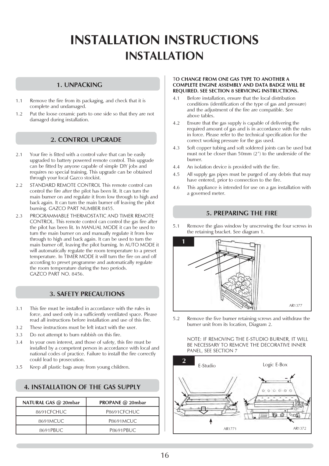
5.preparing the fire
5.1Remove the glass window by unscrewing the four screws in the retaining bracket. See diagram 1.
1
AR1377
5.2Remove the five burner retaining screws and withdraw the burner unit from its location, Diagram 2.
NOTE: IF REMOVING THE
2 | Logic |
AR1771 |
| AR1372 |
|
|
|
|
|
|
16