|
| |
Check continuity between the DC terminals at the rear of the control panel using a circuit tester, under | w | |
theconditionthatthe | DC terminals is mounted on the control panel. (See Fig. | |
When continuity between the DC terminals is confirmed with awire connected across the terminals, and is not confirmedif the wireis removed, the DC terminals are normal. (SeeFig.
Check continuity between the two terminals at the rear side of the circuit breaker using a circuit tester while it is mounted on the control panel.
If continuity is confirmed when the breaker is ON, and no continuity is confirmed when the breaker is OFF, the circuit breakeris normal.
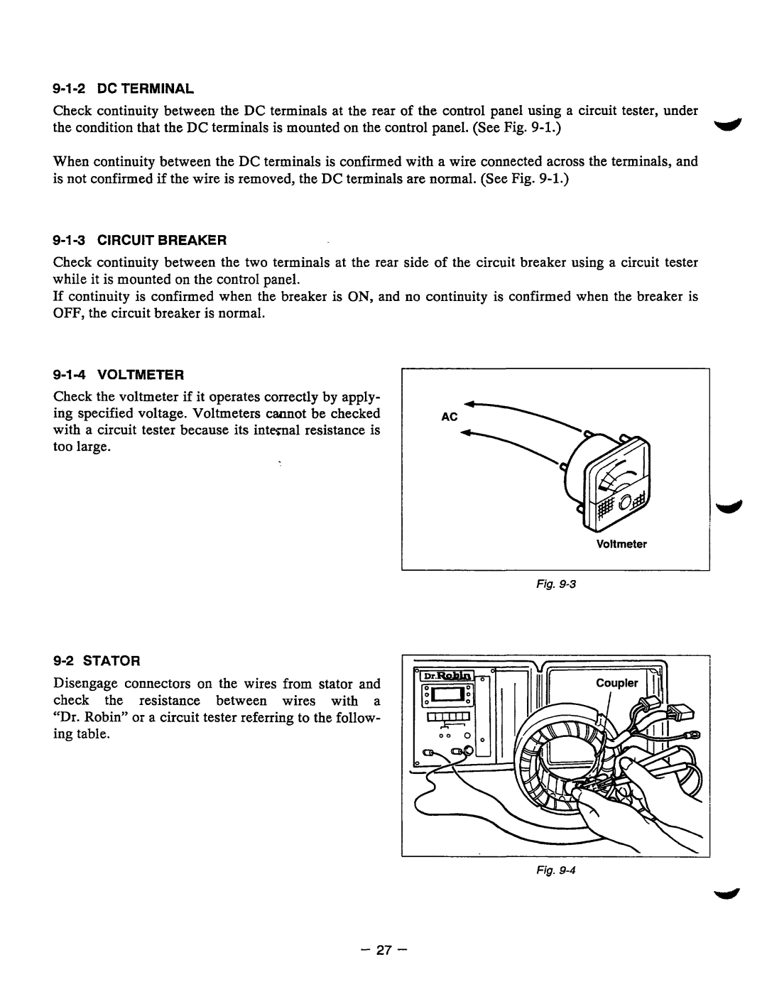
Check the voltmeterif it operates correctlyby apply- ing specified voltage. Voltmeters caunot be checked with a circuit tester because its internal resistance is too large.
AC
Voltmeter
Fig.
Disengageconnectors on thewiresfromstator and checktheresistancebetweenwireswitha
“Dr. Robin” or a circuit tester referring to the follow- ing table.
I
Fig.
- 27 -