3.1.32x7 Configuration
The 2x7 configuration includes two controller modules with seven StorEdge D1000 disk arrays.
3.1.3.1Option Switch
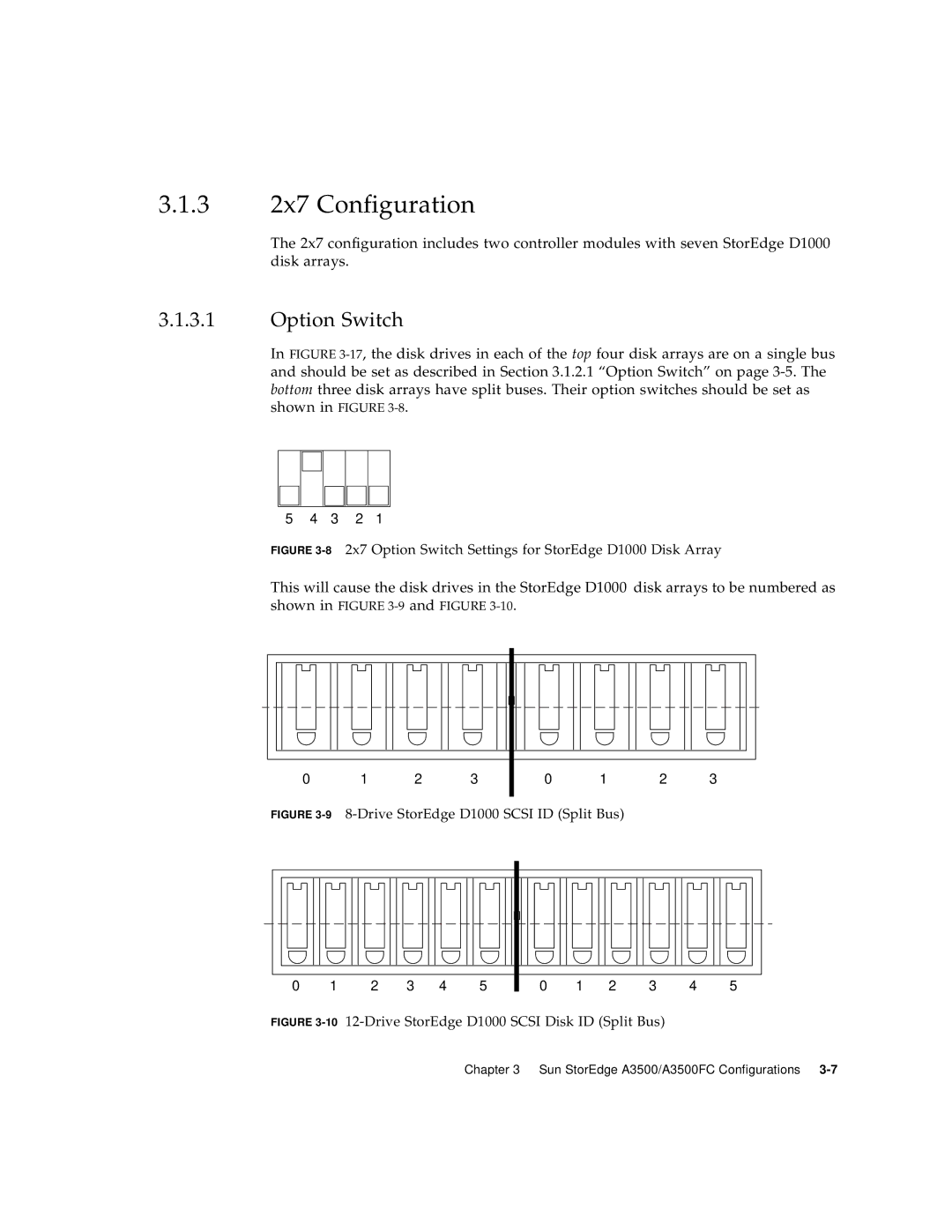
In FIGURE
5 4 3 2 1
FIGURE 3-8 2x7 Option Switch Settings for StorEdge D1000 Disk Array
This will cause the disk drives in the StorEdge D1000 disk arrays to be numbered as shown in FIGURE
0 | 1 | 2 | 3 |
0 1 2 3
FIGURE 3-9 8-Drive StorEdge D1000 SCSI ID (Split Bus)
0 | 1 | 2 | 3 | 4 | 5 |
0 | 1 | 2 | 3 | 4 | 5 |
FIGURE 3-10 12-Drive StorEdge D1000 SCSI Disk ID (Split Bus)
Chapter 3 Sun StorEdge A3500/A3500FC Configurations