3.1.3.2Module ID Switch
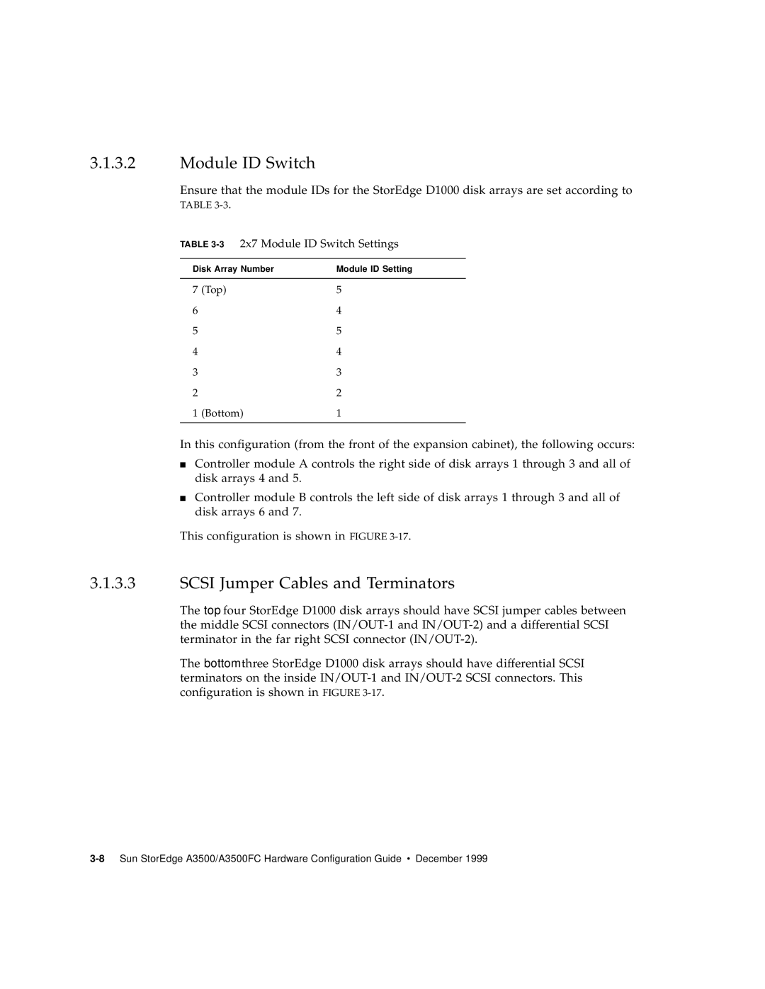
Ensure that the module IDs for the StorEdge D1000 disk arrays are set according to TABLE
TABLE 3-3 2x7 Module ID Switch Settings
Disk Array Number | Module ID Setting | |
|
|
|
7 | (Top) | 5 |
6 |
| 4 |
5 |
| 5 |
4 |
| 4 |
3 |
| 3 |
2 |
| 2 |
1 | (Bottom) | 1 |
|
|
|
In this configuration (from the front of the expansion cabinet), the following occurs:
■Controller module A controls the right side of disk arrays 1 through 3 and all of disk arrays 4 and 5.
■Controller module B controls the left side of disk arrays 1 through 3 and all of disk arrays 6 and 7.
This configuration is shown in FIGURE
3.1.3.3SCSI Jumper Cables and Terminators
The top four StorEdge D1000 disk arrays should have SCSI jumper cables between the middle SCSI connectors
The bottom three StorEdge D1000 disk arrays should have differential SCSI terminators on the inside