3.2.2Power Connections
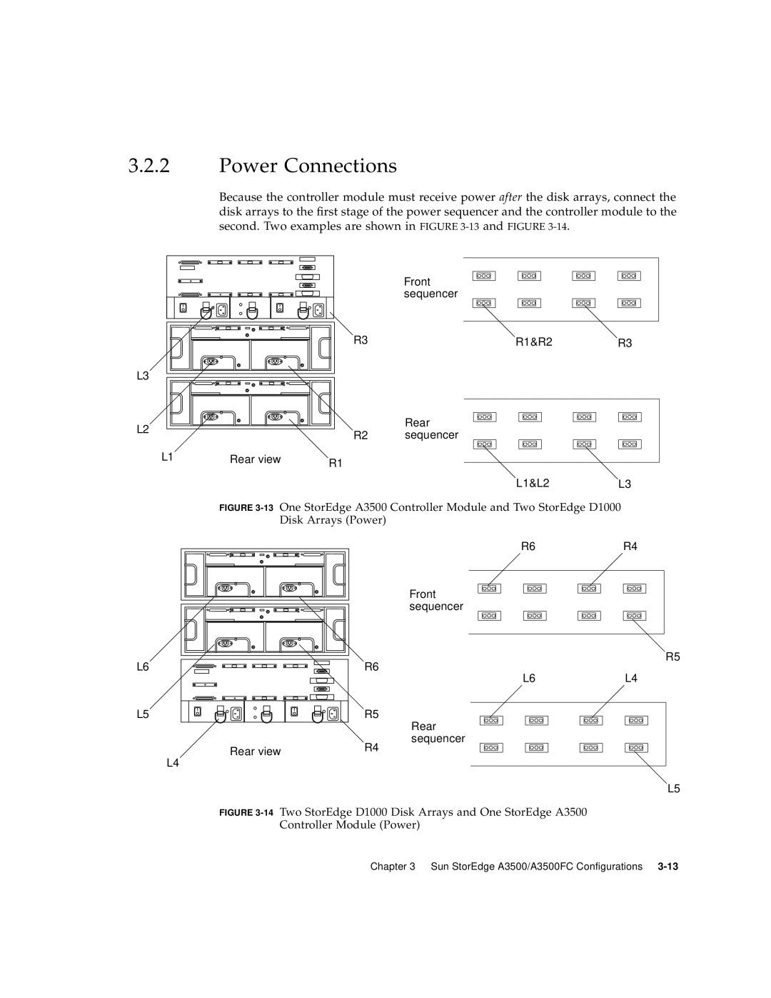
Because the controller module must receive power after the disk arrays, connect the disk arrays to the first stage of the power sequencer and the controller module to the second. Two examples are shown in FIGURE
| Front |
|
| sequencer |
|
R3 | R1&R2 | R3 |
L3 |
|
|
L2 |
|
| Rear |
| R2 | sequencer | |
|
| ||
L1 | Rear view | R1 |
|
|
|
|
L1&L2L3
FIGURE 3-13 One StorEdge A3500 Controller Module and Two StorEdge D1000
Disk Arrays (Power)
L6
L5
Rear view
L4
R6R4
Front sequencer
R5
R6
L6L4
R5
Rear
sequencer
R4
L5
FIGURE 3-14 Two StorEdge D1000 Disk Arrays and One StorEdge A3500 Controller Module (Power)
Chapter 3 Sun StorEdge A3500/A3500FC Configurations
