Registers | S16A User’s Guide |
Input Clock Prescale Registers
The Analog Input Module contains two
192 KHz/(value + 1)
where
value is the channel’s Input Clock Prescale register value, which can range from 0 to 7.
As Analog Input Module registers, these registers are accessed via the UART registers.
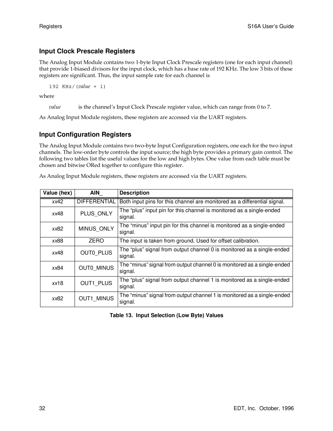
Input Configuration Registers
The Analog Input Module contains two
As Analog Input Module registers, these registers are accessed via the UART registers.
Value (hex) | AIN_ | Description | |
|
|
| |
|
|
| |
xx42 | DIFFERENTIAL | Both input pins for this channel are monitored as a differential signal. | |
|
|
| |
xx48 | PLUS_ONLY | The “plus” input pin for this channel is monitored as a | |
signal. | |||
|
| ||
|
|
| |
xx82 | MINUS_ONLY | The “minus” input pin for this channel is monitored as a | |
signal. | |||
|
| ||
|
|
| |
xx88 | ZERO | The input is taken from ground. Used for offset calibration. | |
|
|
| |
xx48 | OUT0_PLUS | The “plus” signal from output channel 0 is monitored as a | |
signal. | |||
|
| ||
|
|
| |
xx84 | OUT0_MINUS | The “minus” signal from output channel 0 is monitored as a | |
signal. | |||
|
| ||
|
|
| |
xx18 | OUT1_PLUS | The “plus” signal from output channel 1 is monitored as a | |
signal. | |||
|
| ||
|
|
| |
xx82 | OUT1_MINUS | The “minus” signal from output channel 1 is monitored as a | |
signal. | |||
|
| ||
|
|
| |
| Table 13. Input Selection (Low Byte) Values | ||
32 | EDT, Inc. October, 1996 |