Registers | | S16A User’s Guide |
| | |
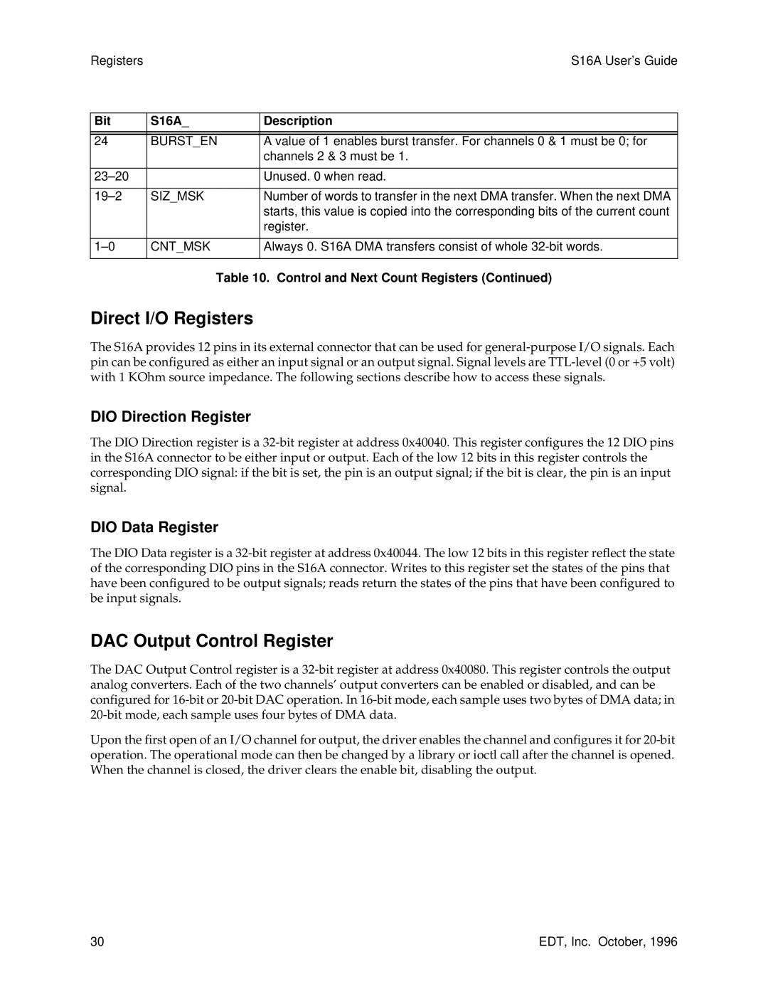
Bit | S16A_ | Description |
| | |
| | |
24 | BURST_EN | A value of 1 enables burst transfer. For channels 0 & 1 must be 0; for |
| | channels 2 & 3 must be 1. |
| | |
23–20 | | Unused. 0 when read. |
| | |
19–2 | SIZ_MSK | Number of words to transfer in the next DMA transfer. When the next DMA |
| | starts, this value is copied into the corresponding bits of the current count |
| | register. |
| | |
1–0 | CNT_MSK | Always 0. S16A DMA transfers consist of whole 32-bit words. |
| | |
Table 10. Control and Next Count Registers (Continued)
Direct I/O Registers
The S16A provides 12 pins in its external connector that can be used for general-purpose I/O signals. Each pin can be configured as either an input signal or an output signal. Signal levels are TTL-level (0 or +5 volt) with 1 KOhm source impedance. The following sections describe how to access these signals.
DIO Direction Register
The DIO Direction register is a 32-bit register at address 0x40040. This register configures the 12 DIO pins in the S16A connector to be either input or output. Each of the low 12 bits in this register controls the corresponding DIO signal: if the bit is set, the pin is an output signal; if the bit is clear, the pin is an input signal.
DIO Data Register
The DIO Data register is a 32-bit register at address 0x40044. The low 12 bits in this register reflect the state of the corresponding DIO pins in the S16A connector. Writes to this register set the states of the pins that have been configured to be output signals; reads return the states of the pins that have been configured to be input signals.
DAC Output Control Register
The DAC Output Control register is a 32-bit register at address 0x40080. This register controls the output analog converters. Each of the two channels’ output converters can be enabled or disabled, and can be configured for 16-bit or 20-bit DAC operation. In 16-bit mode, each sample uses two bytes of DMA data; in 20-bit mode, each sample uses four bytes of DMA data.
Upon the first open of an I/O channel for output, the driver enables the channel and configures it for 20-bit operation. The operational mode can then be changed by a library or ioctl call after the channel is opened. When the channel is closed, the driver clears the enable bit, disabling the output.
30 | EDT, Inc. October, 1996 |