S16A User’s Guide |
| Registers | |||
|
|
|
|
|
|
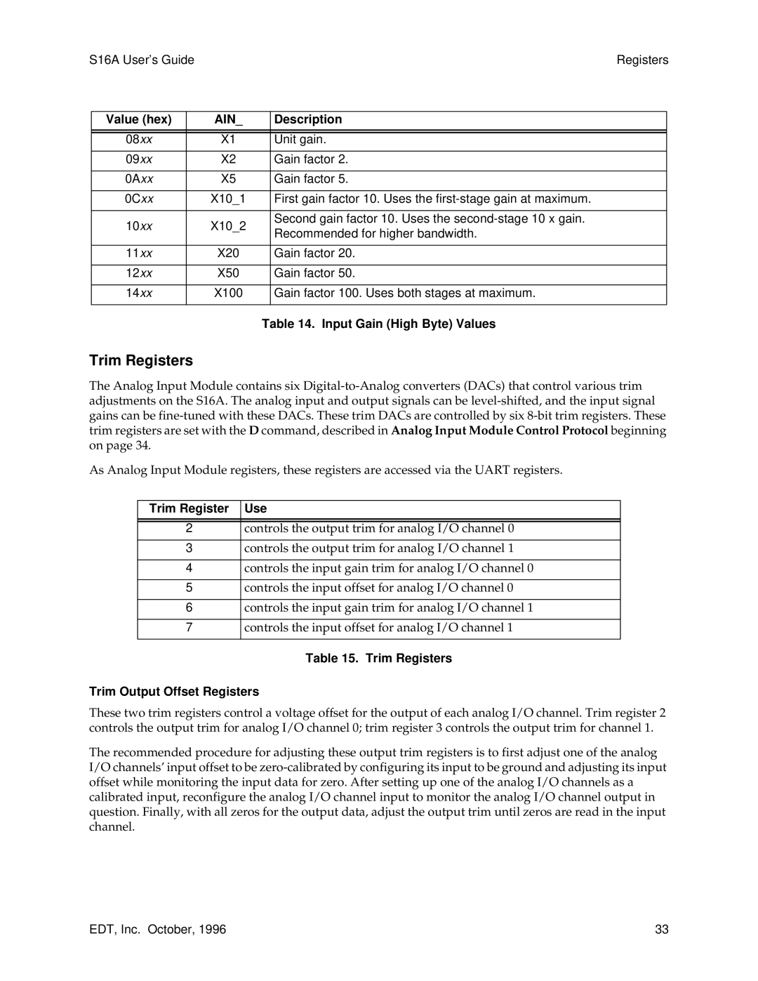
| Value (hex) |
| AIN_ | Description |
|
|
|
|
|
|
|
|
|
|
|
|
|
| 08xx |
| X1 | Unit gain. |
|
|
|
|
|
|
|
| 09xx |
| X2 | Gain factor 2. |
|
|
|
|
|
|
|
| 0Axx |
| X5 | Gain factor 5. |
|
|
|
|
|
|
|
| 0Cxx |
| X10_1 | First gain factor 10. Uses the |
|
|
|
|
|
|
|
| 10xx |
| X10_2 | Second gain factor 10. Uses the |
|
|
| Recommended for higher bandwidth. |
| ||
|
|
|
|
| |
|
|
|
|
|
|
| 11xx |
| X20 | Gain factor 20. |
|
|
|
|
|
|
|
| 12xx |
| X50 | Gain factor 50. |
|
|
|
|
|
|
|
| 14xx |
| X100 | Gain factor 100. Uses both stages at maximum. |
|
|
|
|
|
|
|
Table 14. Input Gain (High Byte) Values
Trim Registers
The Analog Input Module contains six
As Analog Input Module registers, these registers are accessed via the UART registers.
Trim Register | Use |
|
|
|
|
2 | controls the output trim for analog I/O channel 0 |
|
|
3 | controls the output trim for analog I/O channel 1 |
|
|
4 | controls the input gain trim for analog I/O channel 0 |
|
|
5 | controls the input offset for analog I/O channel 0 |
|
|
6 | controls the input gain trim for analog I/O channel 1 |
|
|
7 | controls the input offset for analog I/O channel 1 |
|
|
Table 15. Trim Registers
Trim Output Offset Registers
These two trim registers control a voltage offset for the output of each analog I/O channel. Trim register 2 controls the output trim for analog I/O channel 0; trim register 3 controls the output trim for channel 1.
The recommended procedure for adjusting these output trim registers is to first adjust one of the analog I/O channels’ input offset to be
EDT, Inc. October, 1996 | 33 |