Chapter 5: Advanced Serverboard Setup
PDSMU Quick Reference
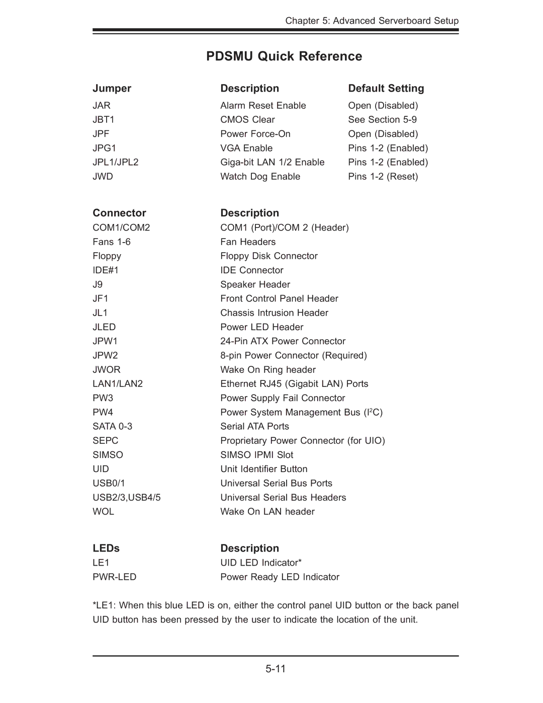
Jumper | Description | Default Setting | |
JAR | Alarm Reset Enable | Open (Disabled) | |
JBT1 | CMOS Clear | See Section | |
JPF | Power | Open (Disabled) | |
JPG1 | VGA Enable | Pins | (Enabled) |
JPL1/JPL2 | Pins | (Enabled) | |
JWD | Watch Dog Enable | Pins | (Reset) |
Connector | Description |
COM1/COM2 | COM1 (Port)/COM 2 (Header) |
Fans | Fan Headers |
Floppy | Floppy Disk Connector |
IDE#1 | IDE Connector |
J9 | Speaker Header |
JF1 | Front Control Panel Header |
JL1 | Chassis Intrusion Header |
JLED | Power LED Header |
JPW1 | |
JPW2 | |
JWOR | Wake On Ring header |
LAN1/LAN2 | Ethernet RJ45 (Gigabit LAN) Ports |
PW3 | Power Supply Fail Connector |
PW4 | Power System Management Bus (I2C) |
SATA | Serial ATA Ports |
SEPC | Proprietary Power Connector (for UIO) |
SIMSO | SIMSO IPMI Slot |
UID | Unit Identifi er Button |
USB0/1 | Universal Serial Bus Ports |
USB2/3,USB4/5 | Universal Serial Bus Headers |
WOL | Wake On LAN header |
LEDs | Description |
LE1 | UID LED Indicator* |
| Power Ready LED Indicator |
*LE1: When this blue LED is on, either the control panel UID button or the back panel UID button has been pressed by the user to indicate the location of the unit.
