SUPERSERVER
5-8 Connector Definitions
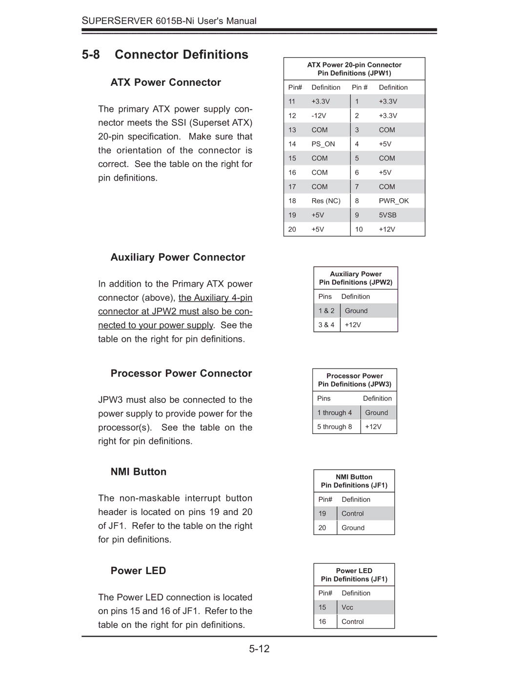
ATX Power Connector
The primary ATX power supply con- nector meets the SSI (Superset ATX)
Auxiliary Power Connector
In addition to the Primary ATX power connector (above), the Auxiliary
Processor Power Connector
JPW3 must also be connected to the power supply to provide power for the processor(s). See the table on the right for pin defi nitions.
NMI Button
The
Power LED
The Power LED connection is located on pins 15 and 16 of JF1. Refer to the table on the right for pin defi nitions.
ATX Power
Pin Definitions (JPW1)
Pin# | Defi nition | Pin # | Defi nition | |
11 | +3.3V | 1 | +3.3V | |
12 |
| +3.3V | ||
2 | ||||
13 | COM |
| COM | |
3 | ||||
14 | PS_ON |
| +5V | |
4 | ||||
15 | COM |
| COM | |
5 | ||||
16 | COM |
| +5V | |
6 | ||||
17 | COM |
| COM | |
7 | ||||
18 | Res (NC) |
| PWR_OK | |
8 | ||||
19 | +5V | 9 | 5VSB | |
20 | +5V | 10 | +12V | |
|
|
|
|
Auxiliary Power
Pin Definitions (JPW2)
Pins | Defi nition | |
1 & 2 | Ground | |
3 & 4 | +12V | |
|
|
Processor Power
Pin Definitions (JPW3)
Pins | Defi nition | |
1 through 4 | Ground | |
5 through 8 | +12V | |
|
|
NMI Button
Pin Definitions (JF1)
Pin# Defi nition
19Control
20Ground
Power LED
Pin Definitions (JF1)
Pin# Defi nition
15Vcc
16Control