Chapter 6: Advanced Chassis Setup
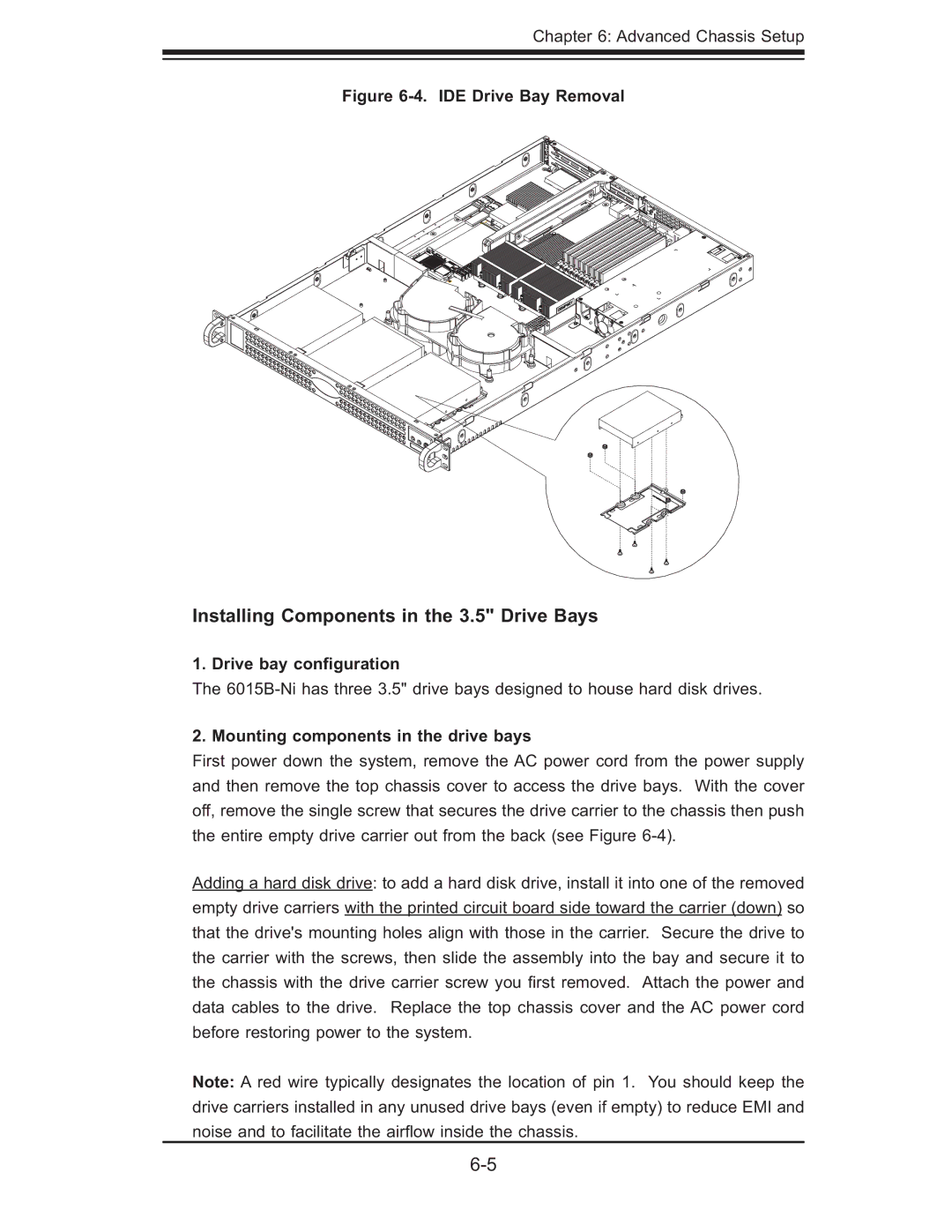
Figure 6-4. IDE Drive Bay Removal
Installing Components in the 3.5" Drive Bays
1. Drive bay configuration
The
2. Mounting components in the drive bays
First power down the system, remove the AC power cord from the power supply and then remove the top chassis cover to access the drive bays. With the cover off, remove the single screw that secures the drive carrier to the chassis then push the entire empty drive carrier out from the back (see Figure
Adding a hard disk drive: to add a hard disk drive, install it into one of the removed empty drive carriers with the printed circuit board side toward the carrier (down) so that the drive's mounting holes align with those in the carrier. Secure the drive to the carrier with the screws, then slide the assembly into the bay and secure it to the chassis with the drive carrier screw you fi rst removed. Attach the power and data cables to the drive. Replace the top chassis cover and the AC power cord before restoring power to the system.
Note: A red wire typically designates the location of pin 1. You should keep the drive carriers installed in any unused drive bays (even if empty) to reduce EMI and noise and to facilitate the airfl ow inside the chassis.