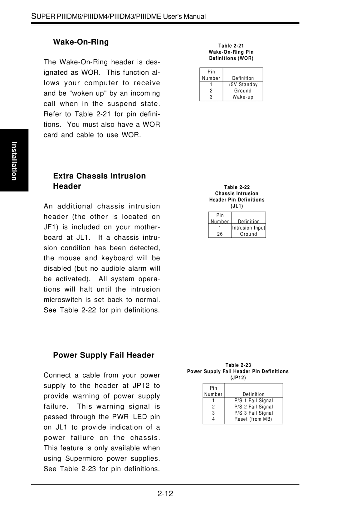
Super PIIIDME, Super PIIIDM4, Super PIIIDM3, Super PIIIDM6 specifications
Super Micro Computer, a prominent player in the server and high-performance computing industries, has introduced a range of motherboards known as the Super PIIIDM4, Super PIIIDME, Super PIIIDM6, and Super PIIIDM3. These motherboards are engineered to cater to various computing needs, from enterprise servers to personal workstations, reinforcing Super Micro's reputation for innovation and reliability.The Super PIIIDM4 motherboard stands out for its support for Intel's latest multi-core processors. It features a robust chipset that enhances overall system stability and performance. With up to 128GB of DDR4 ECC (Error-Correcting Code) memory support, it ensures data integrity and reliability, making it ideal for critical applications that demand uninterrupted service. It also incorporates multiple PCI-E slots for expandability, allowing users to add high-speed networking cards or advanced graphics solutions.
The Super PIIIDME motherboard, designed for minimalist environments, offers a compact form factor without compromising performance. Equipped with multiple SATA III ports, it supports modern storage solutions, including SSDs, which significantly improve data access speeds. The board provides integrated graphics, catering well to general-purpose computing while maintaining low power consumption, a hallmark of Super Micro's design philosophy.
The Super PIIIDM6 motherboard is geared towards high-density server applications. It supports dual CPU configurations, enabling parallel processing for demanding tasks. Featuring enhanced thermal management technologies, including advanced heat sink designs and multiple fan headers, this motherboard ensures optimal cooling even under heavy loads. The Super PIIIDM6 also provides extensive I/O options, including high-speed USB ports, and onboard RAID support, enhancing data redundancy and performance.
Lastly, the Super PIIIDM3 serves as a versatile solution for educational and research institutions, featuring ample expansion options and networking capabilities. It supports legacy PCI slots for compatibility with older hardware, ensuring that institutions can leverage existing infrastructure while transitioning to newer technologies.
In summary, the Super Micro Super PIIIDM series represents a commitment to quality and performance across various applications. These motherboards are designed with the latest features and technologies, ensuring that users can achieve optimal performance and scalability in their computing tasks. Whether for enterprise servers, personal workstations, or educational setups, these motherboards offer a robust foundation for any computing environment.

