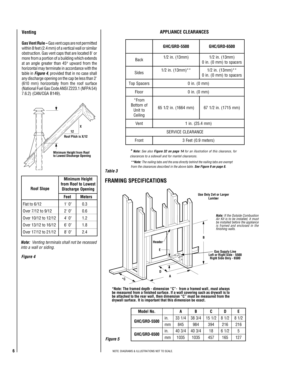
GHC/GRD-5500 specifications
The Superior GHC/GRD-5500 is a cutting-edge machine designed to meet the demands of modern industrial applications. This model integrates advanced technology with robust engineering, making it a reliable choice for various industries, including construction, mining, and heavy-duty manufacturing.One of the standout features of the Superior GHC/GRD-5500 is its powerful hydraulic system, which offers exceptional lifting capabilities. With a lifting capacity of up to 55 tons, it can handle heavy loads effortlessly while ensuring stability and safety. The hydraulic system is designed for efficiency, allowing operators to perform tasks quickly and with precision.
The machine is equipped with a state-of-the-art control system that enhances user experience and operational efficiency. The intuitive interface allows for easy navigation and quick access to various machine settings, ensuring that operators can focus on the task at hand. Furthermore, the GHC/GRD-5500 includes advanced diagnostic capabilities, enabling users to monitor the machine's performance and identify potential issues before they escalate.
In terms of mobility, the GHC/GRD-5500 comes with an innovative track system that provides excellent traction and stability on various terrains. This feature is particularly beneficial in rugged environments where traditional wheeled machines may struggle. The adjustable undercarriage allows for adaptability in tight spaces, improving maneuverability and efficiency.
Safety is paramount in the design of the Superior GHC/GRD-5500. The machine includes multiple safety features, such as an automatic shut-off system, overload protection, and a comprehensive monitoring system that alerts operators to any potential hazards. These safety measures help to ensure the well-being of both the operator and surrounding personnel.
Additionally, the Superior GHC/GRD-5500 is built with durability in mind. Constructed from high-quality materials, it is designed to withstand harsh working conditions and maintain peak performance over extended periods. Routine maintenance is simplified through accessible design, enabling quick servicing to minimize downtime.
In conclusion, the Superior GHC/GRD-5500 is an exemplary machine that combines power, efficiency, and safety. Its advanced hydraulic system, user-friendly control interface, mobility features, and emphasis on safety make it a versatile tool for various industrial applications. As businesses continue to seek reliable solutions, the GHC/GRD-5500 stands out as a top contender in its class.

