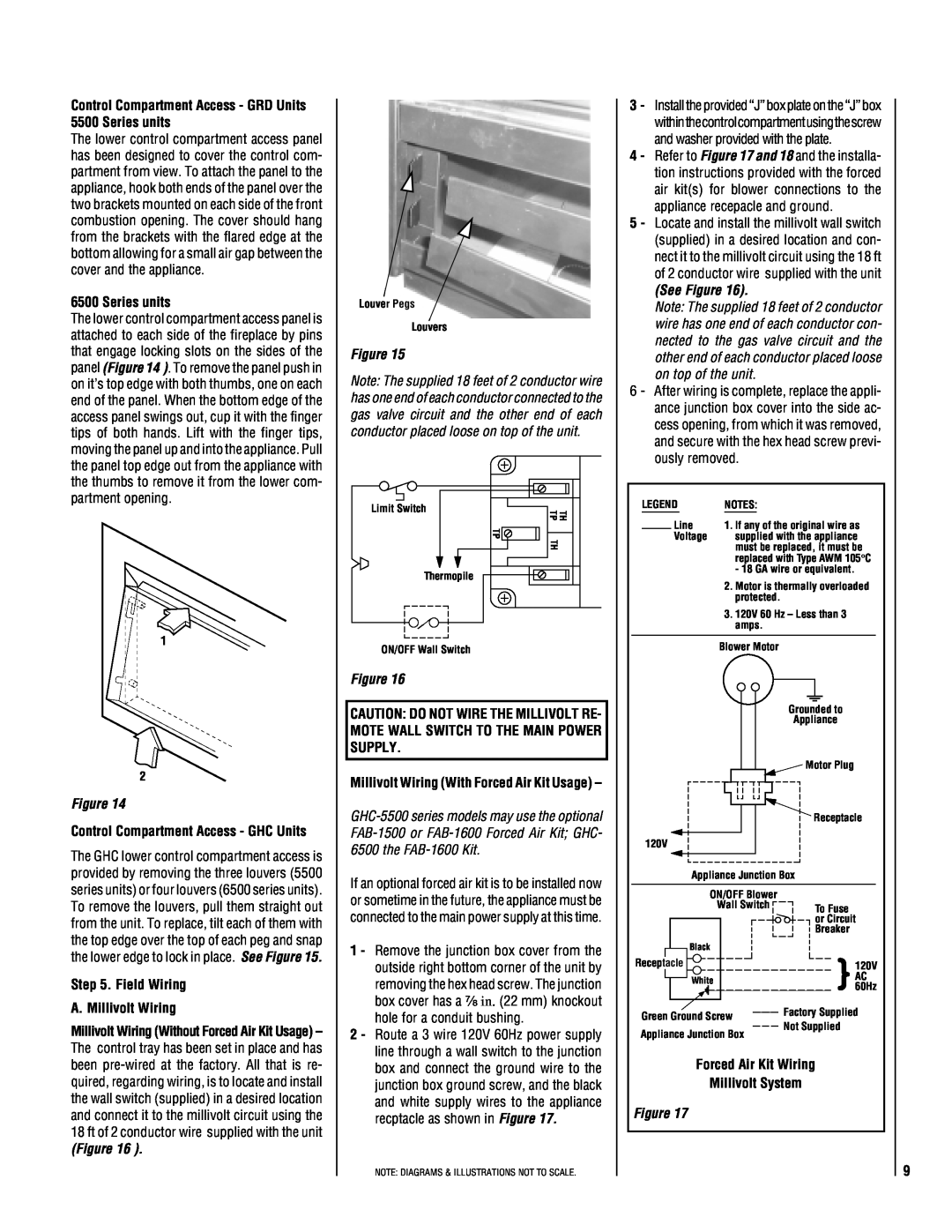
Control Compartment Access - GRD Units 5500 Series units
The lower control compartment access panel has been designed to cover the control com- partment from view. To attach the panel to the appliance, hook both ends of the panel over the two brackets mounted on each side of the front combustion opening. The cover should hang from the brackets with the flared edge at the bottom allowing for a small air gap between the cover and the appliance.
6500 Series units
The lower control compartment access panel is attached to each side of the fireplace by pins that engage locking slots on the sides of the panel (Figure 14 ). To remove the panel push in on it’s top edge with both thumbs, one on each end of the panel. When the bottom edge of the access panel swings out, cup it with the finger tips of both hands. Lift with the finger tips, moving the panel up and into the appliance. Pull the panel top edge out from the appliance with the thumbs to remove it from the lower com- partment opening.
1
2
Figure 14
Control Compartment Access - GHC Units
The GHC lower control compartment access is provided by removing the three louvers (5500 series units) or four louvers (6500 series units). To remove the louvers, pull them straight out from the unit. To replace, tilt each of them with the top edge over the top of each peg and snap the lower edge to lock in place. See Figure 15.
Step 5. Field Wiring
A. Millivolt Wiring
Millivolt Wiring (Without Forced Air Kit Usage) – The control tray has been set in place and has been
(Figure 16 ).
Louver Pegs
Louvers
Figure 15
Note: The supplied 18 feet of 2 conductor wire has one end of each conductor connected to the gas valve circuit and the other end of each conductor placed loose on top of the unit.
Limit Switch | TH TP |
| |
| TP |
| TH |
Thermopile |
|
ON/OFF Wall Switch
Figure 16
CAUTION: DO NOT WIRE THE MILLIVOLT RE- MOTE WALL SWITCH TO THE MAIN POWER SUPPLY.
Millivolt Wiring (With Forced Air Kit Usage) –
If an optional forced air kit is to be installed now or sometime in the future, the appliance must be connected to the main power supply at this time.
1 - Remove the junction box cover from the outside right bottom corner of the unit by removing the hex head screw. The junction box cover has a ⁷⁄₈ in. (22 mm) knockout hole for a conduit bushing.
2 - Route a 3 wire 120V 60Hz power supply line through a wall switch to the junction box and connect the ground wire to the junction box ground screw, and the black and white supply wires to the appliance recptacle as shown in Figure 17.
NOTE: DIAGRAMS & ILLUSTRATIONS NOT TO SCALE.
3- Install the provided “J” box plate on the “J” box withinthecontrolcompartmentusingthescrew and washer provided with the plate.
4 - Refer to Figure 17 and 18 and the installa- tion instructions provided with the forced air kit(s) for blower connections to the appliance recepacle and ground.
5 - Locate and install the millivolt wall switch (supplied) in a desired location and con- nect it to the millivolt circuit using the 18 ft of 2 conductor wire supplied with the unit
(See Figure 16).
Note: The supplied 18 feet of 2 conductor wire has one end of each conductor con- nected to the gas valve circuit and the other end of each conductor placed loose on top of the unit.
6 - After wiring is complete, replace the appli- ance junction box cover into the side ac- cess opening, from which it was removed, and secure with the hex head screw previ- ously removed.
LEGEND | NOTES: | |||
|
|
|
| 1. If any of the original wire as |
|
| Line | ||
|
| Voltage | supplied with the appliance | |
|
|
|
| must be replaced, it must be |
|
|
|
| replaced with Type AWM 105° C |
|
|
|
| - 18 GA wire or equivalent. |
|
|
|
| 2. Motor is thermally overloaded |
|
|
|
| protected. |
|
|
|
| 3. 120V 60 Hz – Less than 3 |
|
|
|
| amps. |
|
|
|
|
|
|
|
|
| Blower Motor |
|
|
|
|
|
|
|
|
|
|
|
|
|
|
|
| Grounded to | ||
|
|
|
|
|
|
|
|
|
|
|
|
|
|
|
| Appliance | ||
|
|
|
|
|
|
|
|
|
|
|
|
|
|
|
| Motor Plug | ||
|
|
|
|
|
|
|
|
|
|
|
|
|
|
|
| Receptacle | ||
|
|
|
|
|
|
|
|
|
|
|
|
|
|
|
| |||
|
|
|
|
|
|
|
|
|
|
|
|
|
|
|
| |||
|
|
|
|
|
|
|
|
|
|
|
|
|
|
|
| |||
|
|
|
|
|
|
|
|
|
|
|
|
|
|
|
| |||
120V |
|
| ||||||||||||||||
|
|
|
|
| Appliance Junction Box | |||||||||||||
|
|
|
|
|
|
|
|
|
|
|
|
|
|
|
|
| ||
|
|
|
|
|
| ON/OFF Blower |
|
| ||||||||||
|
|
|
|
|
| Wall Switch | To Fuse | |||||||||||
|
|
|
|
|
|
|
|
|
|
|
|
|
|
|
| or Circuit | ||
|
|
|
|
|
|
|
|
|
|
|
|
|
|
|
| Breaker | ||
|
|
|
|
| Black |
|
|
|
|
|
|
|
|
|
|
| ||
Recep |
| tacl | e |
|
|
|
|
|
|
|
|
|
|
| 120V | |||
|
|
|
|
| White |
|
|
|
|
|
|
|
|
| AC | |||
|
|
|
|
|
|
|
|
|
|
|
|
|
| }60Hz | ||||
|
|
|
|
|
|
|
|
|
|
|
|
|
|
|
| |||
|
|
|
|
|
|
|
|
|
|
|
|
|
|
|
| Factory Supplied | ||
|
|
|
|
|
|
|
|
|
|
|
|
|
|
|
| |||
Green Ground Screw |
| |||||||||||||||||
Not Supplied | ||||||||||||||||||
Appliance Junction Box | ||||||||||||||||||
|
| |||||||||||||||||
Forced Air Kit Wiring
Millivolt System
Figure 17
9