Operating Instructions |
Part 1: Setting up the DVR Hardware
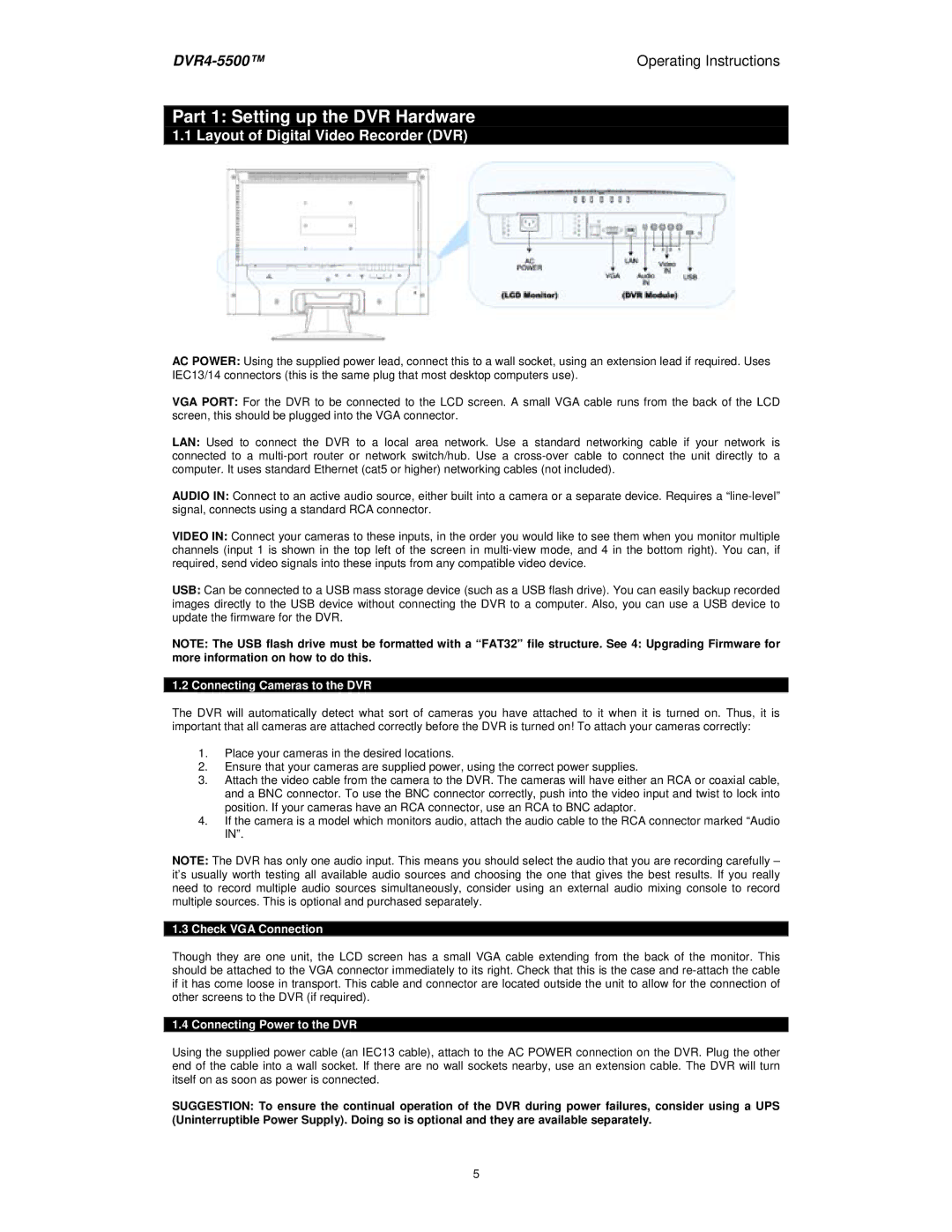
1.1 Layout of Digital Video Recorder (DVR)
AC POWER: Using the supplied power lead, connect this to a wall socket, using an extension lead if required. Uses IEC13/14 connectors (this is the same plug that most desktop computers use).
VGA PORT: For the DVR to be connected to the LCD screen. A small VGA cable runs from the back of the LCD screen, this should be plugged into the VGA connector.
LAN: Used to connect the DVR to a local area network. Use a standard networking cable if your network is connected to a
AUDIO IN: Connect to an active audio source, either built into a camera or a separate device. Requires a
VIDEO IN: Connect your cameras to these inputs, in the order you would like to see them when you monitor multiple channels (input 1 is shown in the top left of the screen in
USB: Can be connected to a USB mass storage device (such as a USB flash drive). You can easily backup recorded images directly to the USB device without connecting the DVR to a computer. Also, you can use a USB device to update the firmware for the DVR.
NOTE: The USB flash drive must be formatted with a “FAT32” file structure. See 4: Upgrading Firmware for more information on how to do this.
1.2 Connecting Cameras to the DVR
The DVR will automatically detect what sort of cameras you have attached to it when it is turned on. Thus, it is important that all cameras are attached correctly before the DVR is turned on! To attach your cameras correctly:
1.Place your cameras in the desired locations.
2.Ensure that your cameras are supplied power, using the correct power supplies.
3.Attach the video cable from the camera to the DVR. The cameras will have either an RCA or coaxial cable, and a BNC connector. To use the BNC connector correctly, push into the video input and twist to lock into position. If your cameras have an RCA connector, use an RCA to BNC adaptor.
4.If the camera is a model which monitors audio, attach the audio cable to the RCA connector marked “Audio IN”.
NOTE: The DVR has only one audio input. This means you should select the audio that you are recording carefully – it’s usually worth testing all available audio sources and choosing the one that gives the best results. If you really need to record multiple audio sources simultaneously, consider using an external audio mixing console to record multiple sources. This is optional and purchased separately.
1.3 Check VGA Connection
Though they are one unit, the LCD screen has a small VGA cable extending from the back of the monitor. This should be attached to the VGA connector immediately to its right. Check that this is the case and
1.4 Connecting Power to the DVR
Using the supplied power cable (an IEC13 cable), attach to the AC POWER connection on the DVR. Plug the other end of the cable into a wall socket. If there are no wall sockets nearby, use an extension cable. The DVR will turn itself on as soon as power is connected.
SUGGESTION: To ensure the continual operation of the DVR during power failures, consider using a UPS (Uninterruptible Power Supply). Doing so is optional and they are available separately.
5