P 10 specifications
T+A Elektroakustik has carved out a niche for itself in the high-end audio market, and one of its standout offerings is the P 10, a high-performance integrated amplifier that embodies the company's commitment to quality and precision.The T+A P 10 is a versatile, multi-channel amplifier that provides a powerful solution for audiophiles seeking pristine sound. It boasts a robust output of up to 250 watts per channel, ensuring that it can drive a wide range of loudspeakers with ease. The design philosophy of T+A emphasizes both aesthetic and functional qualities, resulting in a sleek chassis with high-grade materials that enhance electromagnetic shielding and reduce resonance.
One of the primary features of the P 10 is its incorporation of the latest digital audio technologies. It supports high-resolution audio formats, allowing for playback of DSD, PCM, and other advanced audio files without compromising sound quality. The onboard DAC (digital-to-analog converter) is a standout component, with precision engineering that converts digital signals into audio outputs that are rich in detail and depth.
The P 10 also includes an extensive array of connectivity options. With multiple analogue and digital inputs, including USB, coaxial, and optical connections, it can accommodate various source devices. This versatility makes it suitable for both traditional and modern audio setups. Moreover, the integrated Bluetooth capability enables wireless streaming, allowing users to enjoy music from their smart devices effortlessly.
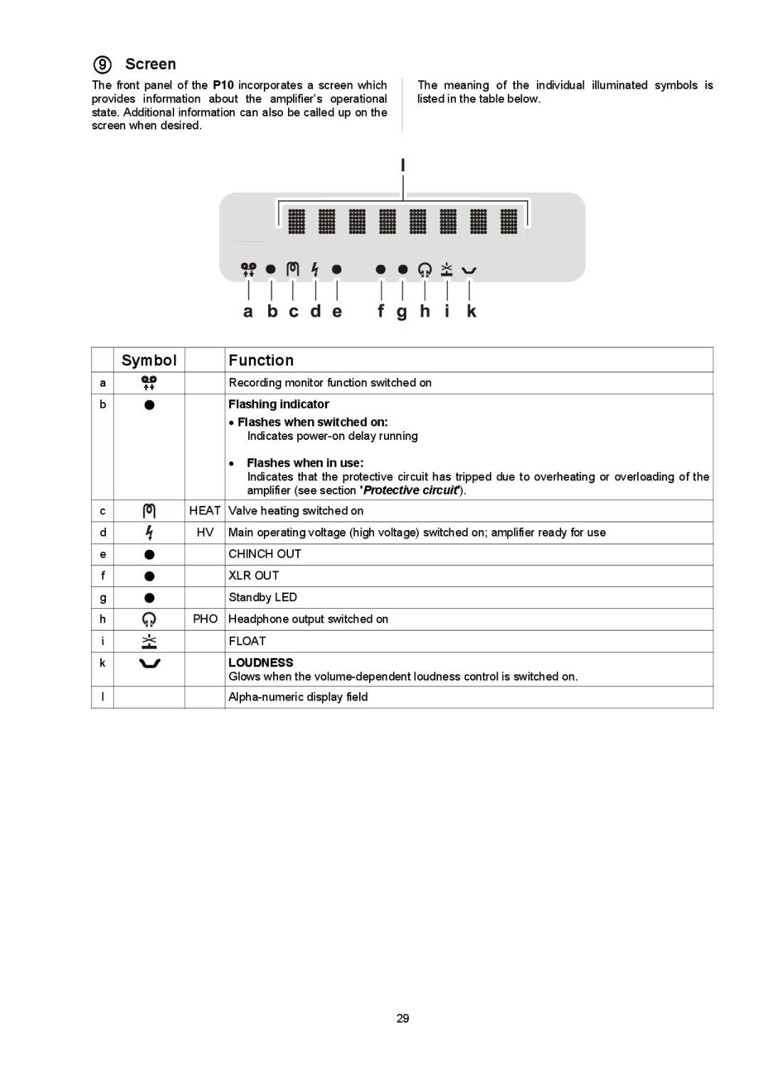
Control and usability have not been overlooked. The P 10 features an intuitive user interface that includes a high-resolution display, making navigation simple and straightforward. Dedicated remote control further enhances the user experience, enabling adjustments from anywhere in the room.
Another significant characteristic of the T+A P 10 is its modular design, which allows for future upgrades. This foresight ensures that users can keep their system current as technology evolves without needing to replace the entire unit.
In conclusion, the T+A Elektroakustik P 10 represents the pinnacle of integrated amplifier design, combining power, versatility, and sophisticated technology into a single unit. For those who demand the best in audio performance, the P 10 is a noteworthy investment, promising a listening experience that transcends ordinary boundaries.

