Features and Controls
|
|
| 5 |
| 4 |
|
|
| 1 |
| 2 |
|
|
|
|
|
|
|
|
|
|
| – |
| – |
|
|
|
| – |
|
| – |
| – |
|
|
|
|
|
|
| 6 | 21 | 22 | 23 | 24 |
| 25 16 | 15 |
|
|
|
| |
40 |
| – | – |
|
|
|
|
|
|
|
| ||
|
|
|
|
|
|
|
|
|
| ||||
|
|
| – |
| – |
|
|
|
|
|
|
|
|
| – | – |
| – | – |
|
|
|
|
|
|
|
|
7 |
|
|
|
|
|
|
|
|
|
|
|
| – |
|
|
|
|
|
|
|
|
|
|
|
|
| |
| – | – |
| – | – |
|
|
|
|
|
|
|
|
8 |
|
|
|
|
|
|
| – |
|
|
|
|
|
9 |
|
|
|
|
|
|
|
|
|
|
|
| |
– | – |
| – | – |
|
|
|
|
|
|
|
| |
41 |
| – |
|
|
|
|
|
|
|
| |||
10 |
| – |
|
|
|
|
|
|
|
|
|
|
|
– | – |
| – | – |
|
|
|
|
|
|
|
| |
39 |
| – | – | – | – |
|
|
|
|
|
|
|
|
|
| – | – | – | – |
|
|
|
|
|
|
|
|
11 | – | – |
| – | – |
|
|
|
|
|
|
|
|
|
|
|
|
|
|
|
|
|
|
|
|
| |
|
|
|
|
|
|
|
|
|
|
|
|
| – |
12 |
|
|
|
|
|
|
|
|
|
|
|
|
|
13 |
|
|
|
|
|
|
|
|
|
|
|
|
|
|
| – | – | – | – |
| – |
|
|
|
|
|
|
|
|
|
|
|
|
|
|
|
| ||||
14 |
|
|
|
|
|
|
| – | – | – | – | – | – |
|
|
|
|
|
|
|
| ||||||
|
|
| 3 |
| 26 | 38 | 20 | 29 | 30 | 31 | 32 | 33 | 34 |
|
|
|
|
|
|
|
| – | – | – | – | – | – |
|
|
|
|
| – | – |
|
|
|
|
|
|
|
| 31 |
|
|
|
|
|
|
|
|
|
|
|
|
28
35
36 ![]() 37 17 18 19
37 17 18 19
27
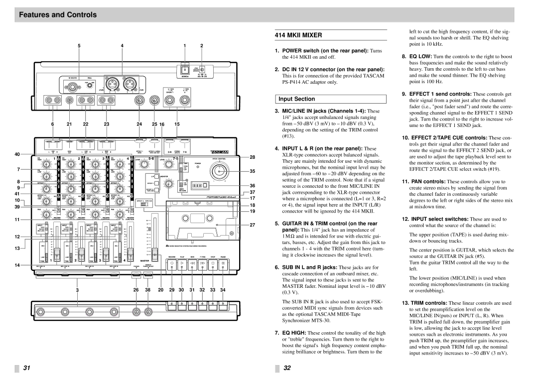
414 MKII MIXER
1.POWER switch (on the rear panel): Turns the 414 MKII on and off.
2.DC IN 12 V connector (on the rear panel):
This is for connection of the provided TASCAM
Input Section
3.MIC/LINE IN jacks (Channels
4.INPUT L & R (on the rear panel): These
5.GUITAR IN & TRIM control (on the rear
panel): This 1/4" jack has an impedance of
1 M Ω and is intended for use with electric gui- tars, basses, etc. Adjust the gain from this jack to channels 1 - 4 with the TRIM control here (turn- ing it clockwise increases the signal level).
6.SUB IN L and R jacks: These jacks are for cascade connection of an outboard mixer, etc. The signal input to these jacks is sent to the MASTER fader. Nominal input level is – 10 dBV (0.3 V).
The SUB IN R jack is also used to accept FSK- converted MIDI sync signals from devices such as the optional TASCAM
7.EQ HIGH: These control the tonality of the high or "treble" frequencies. Turn them to the right to boost the signal's high frequency content empha- sizing brilliance or brightness. Turn them to the
32
left to cut the high frequency content, if the sig- nal sounds too harsh or shrill. The EQ shelving point is 10 kHz.
8.EQ LOW: Turn the controls to the right to boost bass frequencies and make the sound relatively heavy. Turn the controls to the left to cut bass and make the sound thinner. The EQ shelving point is 100 Hz.
9.EFFECT 1 send controls: These controls get their signal from a point just after the channel fader (i.e., "post fader send") and route the corre- sponding channel signal to the EFFECT 1 SEND jack. Turn the control to the right to increase vol- ume to the EFFECT 1 SEND jack.
10.EFFECT 2/TAPE CUE controls: These con- trols get their signal after the channel fader and route the signal to the EFFECT 2 SEND jack, or are used to adjust the tape playback level sent to the monitor section, as determined by the EFFECT 2/TAPE CUE select switch (#19).
11.PAN controls: These controls allow you to create stereo mixes by sending the signal from the channel fader in continuously variable degrees to the left or right sides of the stereo mix at mixdown time.
12.INPUT select switches: These are used to control what the source of the channel is:
The upper position (TAPE) is used during mix- down or bouncing tracks.
The center position is GUITAR, which selects the source at the GUITAR IN jack (#5).
Turn the guitar TRIM control all the way to the left.
The lower position (MIC/LINE) is used when recording microphones/instruments (in tracking or overdubbing).
13.TRIM controls: These linear controls are used to set the preamplification level on the MIC/LINE IN(puts) or INPUT (L, R). When TRIM is pulled full down, the preamplifier gain is low, allowing the jack to accept line level sources such as electronic instruments. As you push TRIM up, the preamplifier gain increases, and when you push TRIM full up, the nominal input sensitivity increases to – 50 dBV (3 mV).