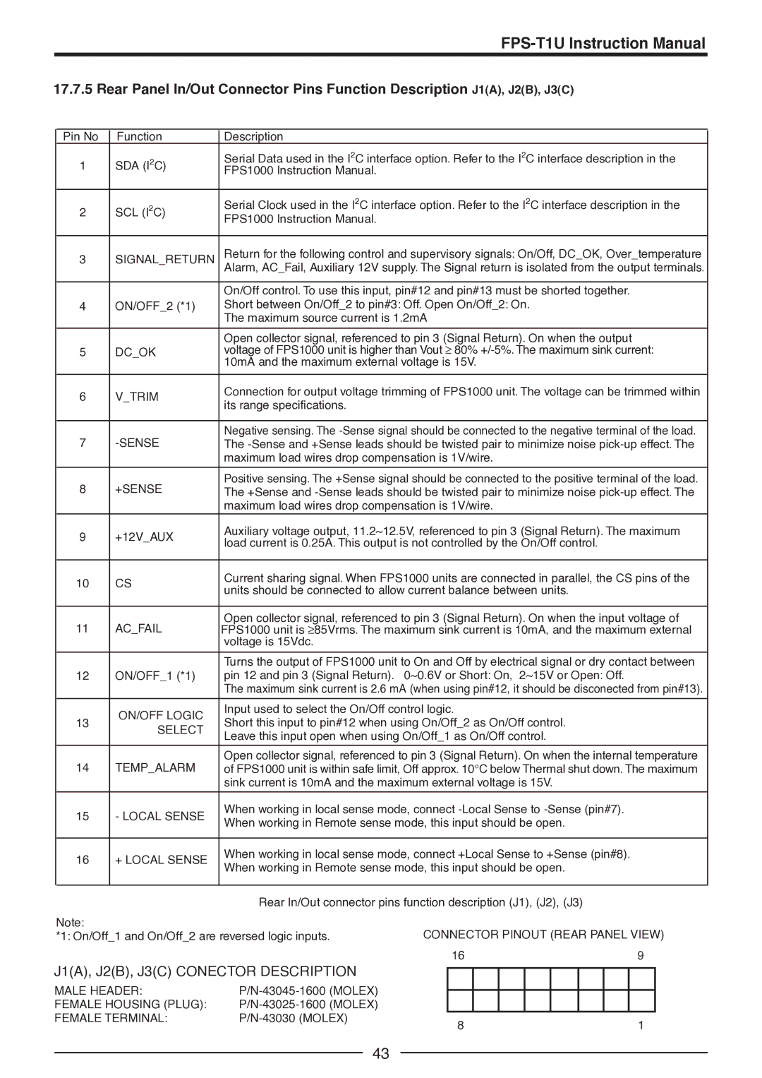
FPS1000-32, FPS-S1U, FPS1000-48, FPS1000-12, FPS-T1U specifications
TDK has established itself as a leading innovator in power supply solutions with its range of FPS series products, specifically designed for various demanding applications. Among these, the FPS1000-24, FPS-T1U, FPS1000-12, FPS1000-48, and FPS-S1U models stand out due to their advanced features, robust technologies, and versatile characteristics.The FPS1000-24, catering to a voltage output of 24V, is ideal for both industrial and commercial applications. It delivers a notable output power of 1000 watts while boasting high efficiency, making it a reliable option for systems that require consistent power with minimal energy loss. The model incorporates advanced protection features including over-voltage, over-current, and short-circuit protection, ensuring that connected devices are safeguarded against potential electrical faults.
Similarly, the FPS1000-12 offers a 12V output with equivalent power ratings, making it suitable for applications such as telecommunications and medical devices where stability and reliability are paramount. This model also emphasizes thermal management, utilizing integrated cooling technologies to maintain optimal performance even under demanding conditions.
The FPS1000-48 distinguishes itself with a 48V output, which is increasingly prevalent in high-density computing environments and server applications. With enhanced scalability, this model allows for multiple unit configurations to support higher load demands while maintaining exceptional efficiency levels.
In addition to the standard offerings, TDK’s FPS-T1U and FPS-S1U models provide intelligent power management solutions. The FPS-T1U, being a compact version, is tailored for space-constrained environments, ensuring high performance without compromising on size. It features built-in monitoring capabilities that allow users to track power usage and efficiency metrics in real-time.
The FPS-S1U is particularly notable for its modular design, enabling easy integration into various systems. This flexibility allows users to adapt the power supply to specific system requirements, enhancing functionality across diverse applications. Both models leverage cutting-edge technology to ensure low standby power consumption, reducing the overall energy footprint.
Overall, TDK’s FPS series exemplifies a commitment to quality, performance, and adaptability, making them ideal candidates for modern power supply needs across industries. With their comprehensive protection mechanisms, efficiency, and innovative designs, they stand as reliable choices for engineers and designers looking to optimize their systems.

