EISA Fast SCSI Caching Adapter
Chapter 1
HARDWARE SETUP
Before plugging the
1.1 Board Layout and Jumper Setting
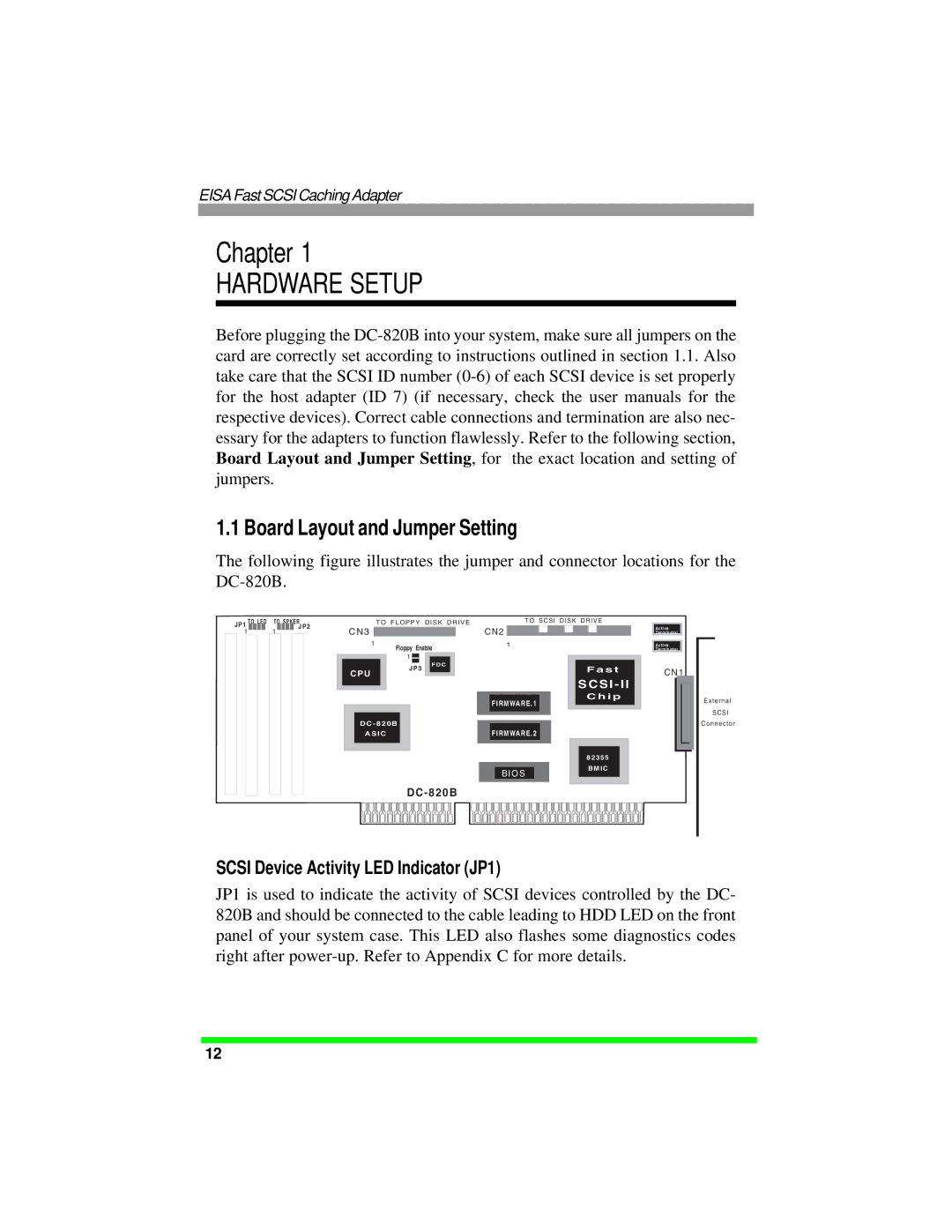
The following figure illustrates the jumper and connector locations for the
JP1 | TO LED |
| TO SPKER |
| TO FLOPPY DISK DRIVE | ||||||||||||
| 1 |
|
|
| 1 |
| JP2 | C N 3 |
|
|
|
|
|
|
| ||
|
|
|
|
|
|
|
|
|
|
| |||||||
|
|
|
|
|
|
|
|
|
|
|
|
| |||||
|
|
|
|
|
|
|
|
|
|
|
|
|
|
|
|
|
|
|
|
|
|
|
|
|
|
|
| 1 | Floppy Enable | ||||||
|
|
|
|
|
|
|
|
|
|
|
| ||||||
|
|
|
|
|
|
|
|
|
| 1 |
|
|
|
|
| ||
|
|
|
|
|
|
|
|
|
| F D C | |||||||
|
|
|
|
|
|
|
|
|
|
|
|
|
|
| |||
TO SCSI DISK DRIVE
C N 2
1
A c tive
Te rm in a to r
A c tive
Te rm in a to r
J P3 |
C PU |
D C - 8 2 0 B
A SI C
D C - 8 2 0 B
FIRMWARE.1
FIRMWARE.2
BIO S
F a s t
SC SI - I I
C h i p
8 2 3 55
B M I C
C N 1
E x t e r n a l
S C S I
C o n n e c t o r
SCSI Device Activity LED Indicator (JP1)
JP1 is used to indicate the activity of SCSI devices controlled by the DC- 820B and should be connected to the cable leading to HDD LED on the front panel of your system case. This LED also flashes some diagnostics codes right after
12
