3 Installation | Model 356WA |
|
|
|
|
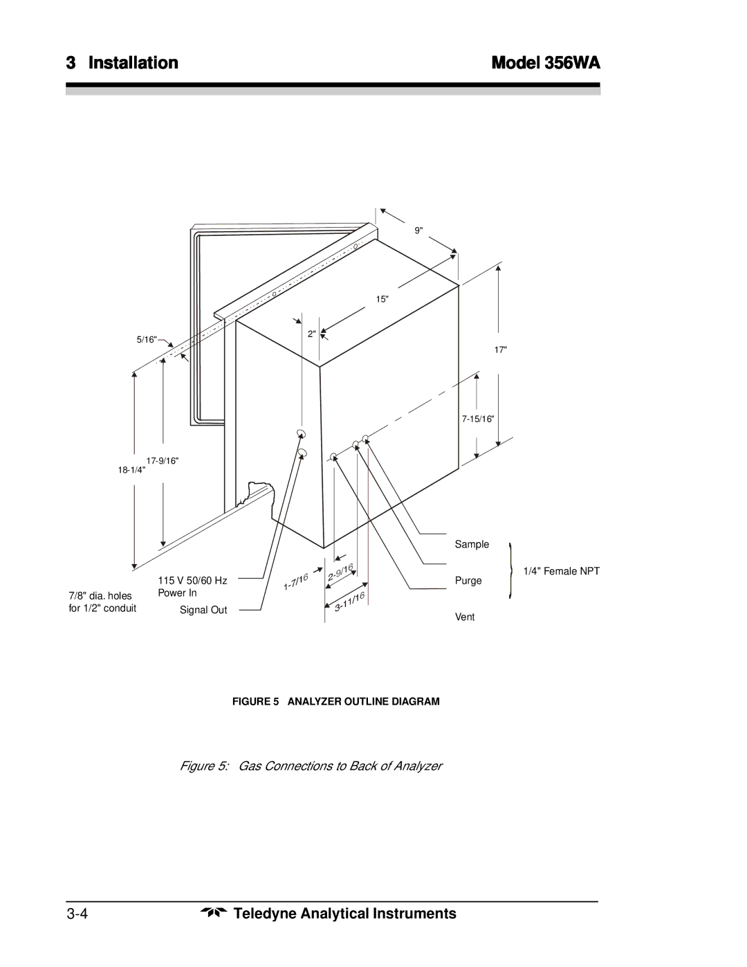
9"
15"
5/16" | 2" |
|
17"
|
| Sample |
| 115 V 50/60 Hz | 1/4" Female NPT |
| Purge | |
7/8" dia. holes | Power In |
|
for 1/2" conduit | Signal Out | Vent |
|
|
FIGURE 5 ANALYZER OUTLINE DIAGRAM
Figure 5: Gas Connections to Back of Analyzer
Teledyne Analytical Instruments |