3 Installation | Model 356WA |
|
|
|
|
Recorder |
|
|
| Signal Leads | |||||||||||||||||
|
|
| (22 ga. Twisted | ||||||||||||||||||
|
|
|
| Pair Shielded | |||||||||||||||||
|
|
|
|
|
|
|
|
| Cable) | ||||||||||||
|
|
|
|
|
|
|
|
|
|
|
|
|
|
|
|
|
|
|
|
|
|
|
|
|
|
|
|
|
|
|
|
|
|
|
|
|
|
|
|
|
|
|
|
|
|
|
|
|
|
|
|
|
|
|
|
|
|
|
|
|
|
|
|
|
|
|
|
|
|
|
|
|
|
|
|
|
|
|
|
|
|
|
|
|
|
|
|
|
|
|
|
|
|
|
|
|
|
|
|
|
|
|
|
|
|
|
|
|
|
|
|
|
|
|
|
|
|
|
|
|
|
|
|
|
|
|
|
|
|
|
|
|
|
|
|
|
|
|
|
|
|
|
|
|
|
|
|
|
|
|
|
|
|
|
|
|
|
|
|
|
|
|
|
|
|
|
|
|
|
|
|
|
|
|
|
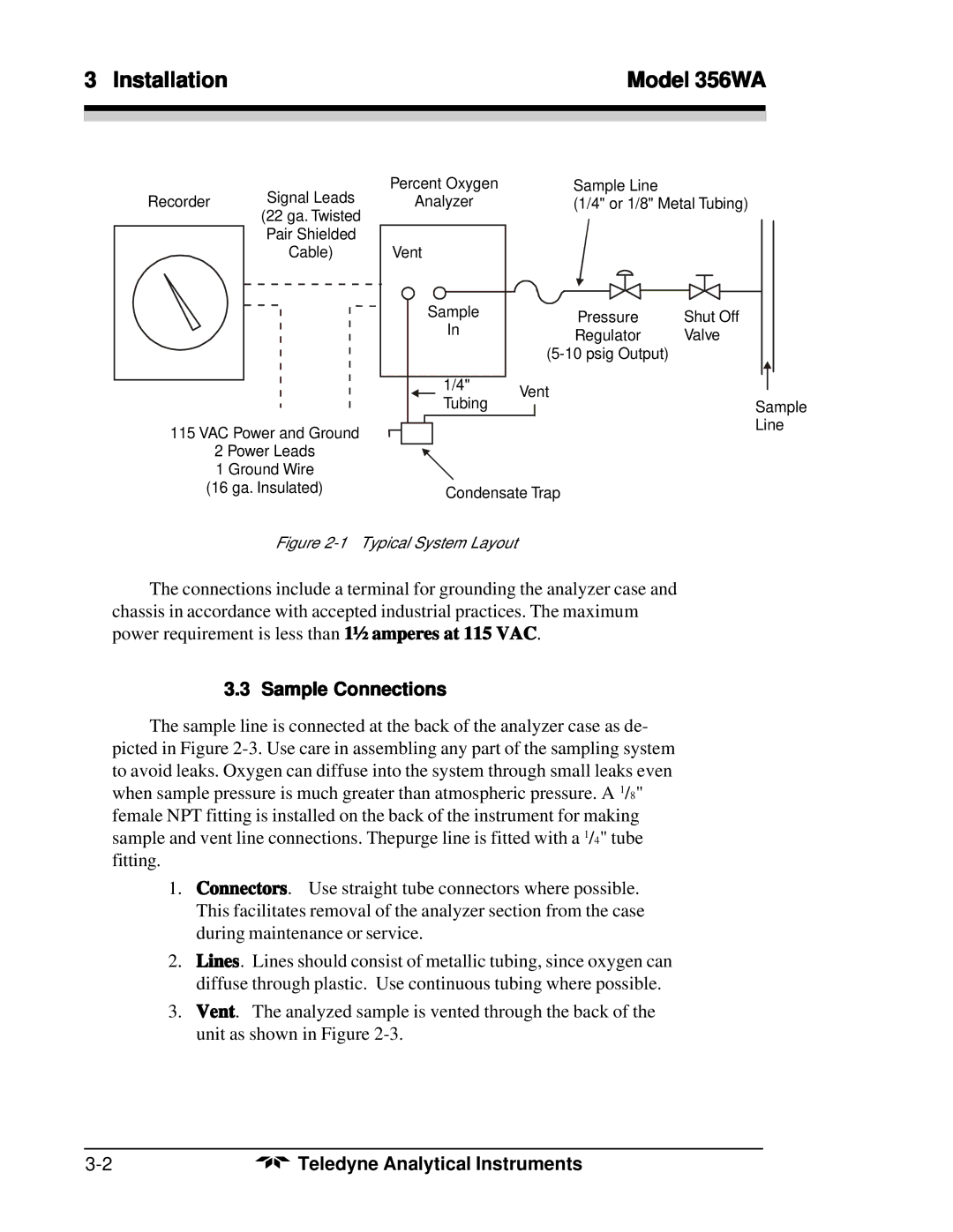
115 VAC Power and Ground
2 Power Leads
1 Ground Wire
Percent Oxygen
Analyzer
Vent
Sample
In
1/4" Tubing
Sample Line
(1/4" or 1/8" Metal Tubing)
Pressure | Shut Off |
Regulator | Valve |
| |
Vent |
|
Sample
Line
(16 ga. Insulated)
Condensate Trap
Figure 2-1 Typical System Layout
The connections include a terminal for grounding the analyzer case and chassis in accordance with accepted industrial practices. The maximum power requirement is less than 1½ amperes at 115 VAC.
3.3 Sample Connections
The sample line is connected at the back of the analyzer case as de- picted in Figure
1.Connectors. Use straight tube connectors where possible. This facilitates removal of the analyzer section from the case during maintenance or service.
2.Lines. Lines should consist of metallic tubing, since oxygen can diffuse through plastic. Use continuous tubing where possible.
3.Vent. The analyzed sample is vented through the back of the unit as shown in Figure
Teledyne Analytical Instruments |