Users Reference Manual
Page
Users Reference Manual
Trademark Acknowledgements
Table of Contents
Operation
Configuration
Vertical Format Units
Bell
Programming
Interfaces
Ribbonminder
What This Manual Contains
Switches and Indicators
Viii P9012 Multinational Users Reference Manual
Introduction
Features
Chapter Overview
Optional Features
Line Matrix Printing
Character Formation
P9012 Print Rate LPM
Print Rate
Plot Rate
Overview
Chapter Operation
Operation Features
Alphanumeric Message Display
Power Switch
Control Panel
Status Lamps
Status Lamps Alphanumeric Message Display
On Line Switch
VFU Loaded Indicator
Clear Switch and Check Indicator
LPI Switch
Paper ADV Switch
RUN/STOP
Menu UP, Menu DOWN, NEXT, and Prev Switches
Forms Length
Print Mode
Loading Paper
Loading Paper Operation
Setting Top-of-Form Forward Paper Motion
Setting Top-Of-Form
Setting Top-of-Form Reverse Paper Motion
Paper Stacking
Front Paper Fence Installation Operation
Paper Tent Installation
Replacing The Ribbon
Unloading Paper
Page
To Set Forms Length in Lines
Setting Forms Length
To Set Forms Length in Inches
On Line DP AT 10 CPI
Selecting Print Mode
Hex Code Printout
Setting Line Spacing
Printer Reset
Running the Self-Test
Operator Correctable Faults
Fault Condition Messages
Program Prom Novram Font Prom
Field Service Required
Operation
Configuration Menus
Chapter Configuration
Lock/Unlock Printer Configuration
Configuration Printout
Sample Configuration Printout
Factory Default Configuration Values
Configuration Procedure
Load Configuration Values
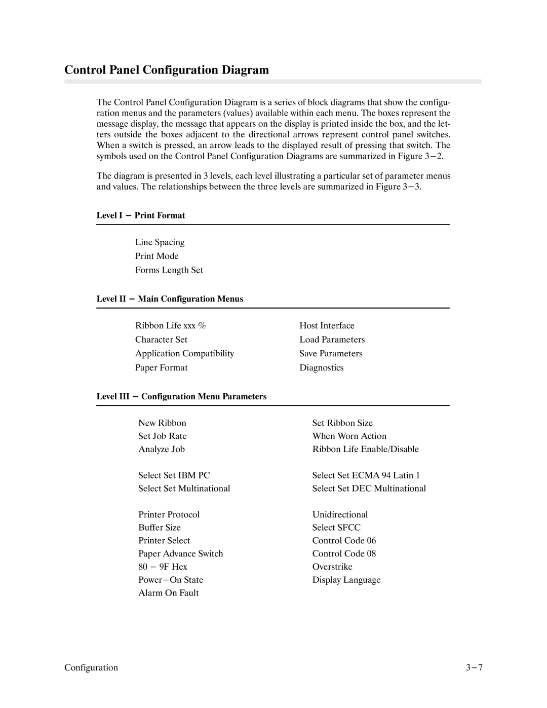
Control Panel Configuration Diagram
Page
Control Panel
Offline Ready
Level
Level I Print Format
Level II Main Configuration Menus
Level III Configuration Menu Parameters
Control Panel Configuration Diagram sheet 4
Control Panel Configuration Diagram sheet 5
Control Panel Configuration Diagram sheet 6
Control Panel Configuration Diagram sheet 7
Control Panel Configuration Diagram sheet 8
Control Panel Configuration Diagram sheet 9
Control Panel Configuration Diagram sheet 10
Control Panel Configuration Diagram sheet 11
Control Panel Configuration Diagram sheet 12
Control Panel Configuration Diagram sheet 13
Control Panel Configuration Diagram sheet 14
Control Panel Configuration Diagram sheet 15
Control Panel Configuration Diagram sheet 16
Control Panel Configuration Diagram sheet 17
Configuration
Plotting a Bit Image Pattern
Chapter Graphics
Serial Matrix Compatible Bit Image Graphics
Bit Image Pattern Plan
How Bit Image Graphics Are Produced
Vertical Data Byte Pattern
Bit Image Density
Data
Bit Image Programming Format
ESC
Plot Density
Series Compatible Plot Mode
Bit Image Sample Program
Normal Density Plot Double Density Plot
ODD DOT Plot Data Byte
Plot Data Byte Format
Even DOT Plot Data Byte
Double Density Plot
Plot Data Line Format
Normal Density Plot
Graphics
Next N Lprint
Plotting the Data
Plot Data Byte Dot Patterns
@ABCDEFGHIJKLMNOPQR
To Exit the P-Series Plot Mode
Combining Graphics and Text
Dvfu
Chapter Vertical Format Units
General VFU Programming
Channel Assignment
Series Evfu
VFU Load/Save/Clear
Start Load Code 1E or 6E Hex
End Load 1F or 6F Hex
Using the Evfu
NUL TOF SOH STX ETX EOT ENQ ACK BEL
DLE TOF DC1 DC2 DC3 DC4 NAK SYN ETB Can SUB ESC
Clearing the Evfu Memory
Relative Line Slewing
SUB ESC
DLE DC1 DC2 DC3 DC4 NAK SYN ETB Can
Start Load Code 6C, 6D, or 6E Hex
Clearing the Dvfu Memory
Using the Dvfu
End Load Code 6F Hex
NUL SOH STX ETX EOT ENQ ACK BEL
DC1 DC2 DC3 DC4 NAK SYN ETB Can
Start Load Code 6D Hex
LPI Byte
DLE
End Load 6F Hex
Clearing the Nvfu Memory
Using the Nvfu
Start Load Code 1D Hex
Cvfu
Second Data Byte
End Load Code 1E Hex
First Data Byte
SOH STX ETX EOT ENQ ACK BEL
Using the Cvfu 1F Hex
Clearing the Cvfu Memory
Relative Line Slewing
DC1 DC2 DC3 DC4 NAK SYN ETB Can SUB ESC
Serial Matrix Vertical Formatting
Executing Vertical Tabs
Quantity
Vertical Tab Positions
Part Number
Part Name
Chapter Programming
Overstrike/Overlay Mode
Special Function Control Code Control Code Header
Control Code Functions
Attribute Set and Reset Codes
Control Code Reference Index
ESC SI
Print Mode Function Series Serial
Sfcc G ESC G
Sfcc H ESC H
Sfcc Pset
Function Series Serial
Sfcc Oset
Sfcc R ESC R
Backspace
Bell
Bit Image Mode, Single Density
Bit Image Mode, Double Density
Bit Image Mode, Double Density Double Speed
Bit Image Mode, Quadruple Density
Sfcc 6A
Bold Print
Sfcc G
Sfcc H
Bold Print Reset
Cancel
Define CR Code CR=CR+LF
Carriage Return
Define CR Code CR=CR
Character Pitch 10 CPI
Character Pitch 12 CPI
Ebcdic
Character Set Select
Ecma DEC IBM PC
Ascii USA
Extended Character Set Select z 030 131 232 333
Page
Character Set Select 80-9F = Control Codes
Character Set Select 80-9F = Printable Symbols
Character Set Select 80-9F = Printable Symbols
Sfcc ESC R Ecma DEC
Character Set Select International Languages
Character Set Select International Languages
Character Set Select Ecma 94 Latin 1 Extended
Condensed Print
Print attributes are not affected
Condensed Print Reset
Delete
Download a Language
Able symbol code point
Language command
Print line lowercase descenders
Download a Character
Elongated Double High Print 1 line
Sfcc E
Emphasized Print
Sfcc F
Emphasized Print Reset
Expanded Double Wide Print
Sfcc 6B
Expanded Double Wide Print One Line Only
Sfcc 6E
Extended Character Set
Sfcc SO Sfcc 0E
Sfcc 6F
Extended Character Set Cancel Primary Character Set Select
Sfcc SI Sfcc 0F
Form Feed
Forms Length Set Inches
Forms Length Set Lines
Horizontal Tab
Horizontal Tab Set
Line Feed
Positioned at character column
Line Feed n/216 Inch One Line Only
Line Spacing 1/6 Inch
Line Spacing 1/8 Inch 8 lpi
Patibility
Line Spacing 8 or 10.3 lpi One Line Only
Line Spacing 7/72 Inch
Line Spacing n/72 Inch
Would reflect 4.3 lpi spacing
Line Spacing n/216 Inch
Overscoring
Plot, Even Dot P-Series High Density Graphics
Plot mode information Example
Tion Example
Plot, Odd Dot P-Series Normal Density Graphics
Sfcc @
Print Mode/Pitch Selection
NLQ HSB HSC OCR-A OCR-B
Print
Mode
Printer Select
Printer Deselect
RibbonMinder, Enable/Disable
RibbonMinder, Set Job Rate
RibbonMinder, When Worn Action
Skip-Over Perforation
Skip-Over Perforation Cancel
Superscript/Subscript Printing
Sfcc T
Superscript/Subscript Printing Reset
Underline
VFU Commands P-Series
Vertical Tab
Tion is ignored
Vertical Tab Set/Clear Serial Matrix
Dataproducts Parallel Interface
Dataproducts Interface Signals
Chapter Interfaces
Output Input Signal PIN
Centronics Parallel Interface
Dataproducts Parallel Interface Configuration
Centronics Interface Signals
RS-232 Serial Interface
Centronics Parallel Interface Configuration
Alternate Terminating Resistors
RS-232 Interface Signals
RS-232 Serial Interface Protocols
RS-232 Serial Interface Configuration
Page
Interior Cleaning
Chapter Routine Service & Diagnostics
Cleaning
Exterior Cleaning
Routine Service & Diagnostics
Cleaning the Paper Motion Detector
Cleaning the Paper Motion Detector
Running the Self-Tests
Printer Self-Tests
Fault Messages
Page
Explanation Action
Fault Operator Corrective Displayed
DP AT 10 CPI On Line
Chapter Ribbonminder T
Overview
On Line
Current
Fault Condition Change Ribbon
Enter Switch Not Locked
Analyzing a Job
Ribbon Life Change Ribbon
Ribbon Life 100% Enable Action
Ribbon Life AUD/VIS Alarm Visual Alarm Stop Printer
Ribbon Life Analyze JOB
Offline 400A Ready
Current NEW Size
Offline 1000A Ready
Analyze JOB NEW Rate
Running a Job
Ribbon Life
Enter Switch Unlocked
Ribbon Life 100% NEW Ribbon
Ribbon Life 100% AUD/VIS Alarm
Ribbon Life 100% Visual Alarm
Ribbon Life 100% Stop Printer
Offline 100% Ready
Multiple Jobs on the Same Ribbon
Ribbon Life 43% NEW Ribbon
Changing a Ribbon Early
Ribbon Life 100% Change Ribbon
Host Control
SET JOB Rate
Procedure
Application Hints
RibbonMinder Diagram
RibbonMinder
Selecting Extended Character Set Ecma
Chapter Multinational Character Sets
Selecting the Character Set and Language
Downloading Languages and Characters
OCR-A and OCR-B
Multinational Character Set Diagram
Character Address Table Character Library
+ Ê
Numeric Character Location Listing
Page
Page
Lowercase O with Acute Accent Mark
Page
Page
Page
Page
Page
Page
Page
Used in other Printronix printer models
Alphabetical Character Location Listing
Page
Page
Page
Page
Page
Lowercase O with Acute Accent Mark
Page
Page
Page
Page
Page
10-30 Multinational Character Sets
Power Requirements
Chapter Installation
Site Requirements
Shipping Restraints
Shipping Restraint Removal 11-4 Installation
Chain Assembly Installation 11-5
Paper Stacking Chain Assembly Installation
Cable Connections
Cable Connections 11-6 Installation
Preliminary Test
11-8 Installation
Appendix a Standard Ascii Character Chart
10-A-2
Appendix B Character Sets
IBM PC Character Set Charts
ETX DC3
NUL
IBM PC Extended Set Series Emulation 80-9F=Control Codes
B3 B2 B1 ROW 100 120 140 160
IBM PC Extended Set Series Emulation 80-9F=Printable Symbols
DEL
NUL
100 116 105 125 145 165 101 117 106 126 146 166
Bits
Language
IBM PC International Languages Substitution Table
Multinational Character Set Charts
114 103 123 143 163
NUL DLE
Bits
KEY
177 111 127
STX
100 116 105 125 145 165 101 117 106 126 146 166
KEY
Multinational Primary Character Set in OCR-A
Multinational Extended Character Set in OCR-A
Multinational Primary Character Set in OCR-B
Multinational Extended Character Set in OCR-B
Ascii Ebcdic
Multinational International Languages Substitution Table
ECMA-94 Latin 1 Character Set Charts
Bits
144 160 176 192 208 224 240 201 221 241 261 301 321 341 361
203 223 243 263 303 323 343 363 131
KEY
@/3
11@
NUL DLE
ESC
KEY
KEY
@/3
ESC
DEL
NUL
ACK
KEY
STX
ACK
NUL DLE
ESC
KEY
KEY
@/3
ESC
ECMA-94 Latin 1 International Languages Substitution Table
DEC Multinational Character Set Charts
Bits
206 226 246 266 306 326 346 366 134 150 166 182 198 214 230
Bits
ESC
DEL
NUL
100 116 105 125 145 165 101 117 106 126 146 166
KEY
DEC Multinational International Languages Substitution Table
Printer Dimensions
Appendix C Specifications
Printing Characteristics
Physical Characteristics
Performance
Environmental Characteristics
Temperature
Electrical Characteristics
Miscellaneous
Interfaces
Forms
Ascii Ascii USA Ebcdic
Cleaning
Character Sets
Appendix
Sfcc R ESC R Sfcc Pset
Appendix D Control Code Cross Reference
Alphabetical By Function
Function Series Serial Emphasized Print Reset
Alphabetical By P-Series Code
Alphabetical By Serial Matrix Code
Line Spacing n/72 Inch as set by ESC a
Appendix
Appendix E Downloading Characters
Procedure
NLQ HSB HSC OCR-A OCR-B
HSB10
NLQ10
NLQ12
NLQ15
Example 1 Characters with No Attributes
Examples
Page
Example 2 Characters with Descenders
Cenders. The semicolon is the hexadecimal data terminator
Example 3 Characters with Extenders
Page
Appendix
Appendix F Hardware Jumper Configuration
Figure F-1. Side Panel Removal Appendix
Side Panel Removal
Removing the DCU Pcba
Figure F-2. Removing the DCU Pcba Appendix
IBM PC, B-2
Index
Cvfu
Index-2
Nvfu
INCHES, Sfcc
LINES, Sfcc
Index-4
DCU PCBA, F-3
Index-5
VFU
Index-6
Page
Printronix