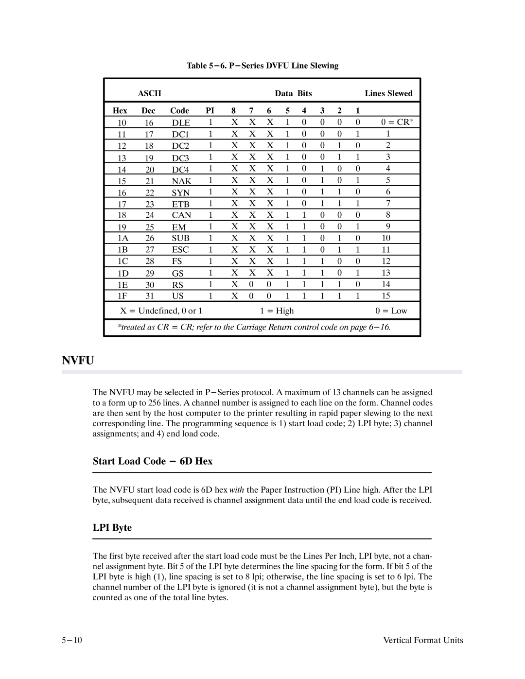
Table
| ASCII |
|
|
|
|
| Data Bits |
|
|
| Lines Slewed | |
|
|
|
|
|
|
|
|
|
|
|
|
|
Hex | Dec | Code | PI | 8 | 7 | 6 | 5 | 4 | 3 | 2 | 1 |
|
10 | 16 | DLE | 1 | X | X | X | 1 | 0 | 0 | 0 | 0 | 0 = CR* |
11 | 17 | DC1 | 1 | X | X | X | 1 | 0 | 0 | 0 | 1 | 1 |
12 | 18 | DC2 | 1 | X | X | X | 1 | 0 | 0 | 1 | 0 | 2 |
13 | 19 | DC3 | 1 | X | X | X | 1 | 0 | 0 | 1 | 1 | 3 |
14 | 20 | DC4 | 1 | X | X | X | 1 | 0 | 1 | 0 | 0 | 4 |
15 | 21 | NAK | 1 | X | X | X | 1 | 0 | 1 | 0 | 1 | 5 |
16 | 22 | SYN | 1 | X | X | X | 1 | 0 | 1 | 1 | 0 | 6 |
17 | 23 | ETB | 1 | X | X | X | 1 | 0 | 1 | 1 | 1 | 7 |
18 | 24 | CAN | 1 | X | X | X | 1 | 1 | 0 | 0 | 0 | 8 |
19 | 25 | EM | 1 | X | X | X 1 1 0 0 1 | 9 | |||||
1A | 26 | SUB | 1 | X | X | X | 1 | 1 | 0 | 1 | 0 | 10 |
1B | 27 | ESC | 1 | X | X | X | 1 | 1 | 0 | 1 | 1 | 11 |
1C | 28 | FS | 1 | X | X | X 1 1 1 0 0 | 12 | |||||
1D | 29 | GS | 1 | X | X | X | 1 | 1 | 1 | 0 | 1 | 13 |
1E | 30 | RS | 1 | X | 0 | 0 | 1 | 1 | 1 | 1 | 0 | 14 |
1F | 31 | US | 1 | X | 0 | 0 | 1 | 1 | 1 | 1 | 1 | 15 |
X = Undefined, 0 or 1 |
|
|
| 1 = High |
|
|
|
| 0 = Low | |||
*treated as CR = CR; refer to the Carriage Return control code on page
NVFU
The NVFU may be selected in
Start Load Code - 6D Hex
The NVFU start load code is 6D hex with the Paper Instruction (PI) Line high. After the LPI byte, subsequent data received is channel assignment data until the end load code is received.
LPI Byte
The first byte received after the start load code must be the Lines Per Inch, LPI byte, not a chanF nel assignment byte. Bit 5 of the LPI byte determines the line spacing for the form. If bit 5 of the LPI byte is high (1), line spacing is set to 8 lpi; otherwise, the line spacing is set to 6 lpi. The channel number of the LPI byte is ignored (it is not a channel assignment byte), but the byte is counted as one of the total line bytes.
Vertical Format Units |
