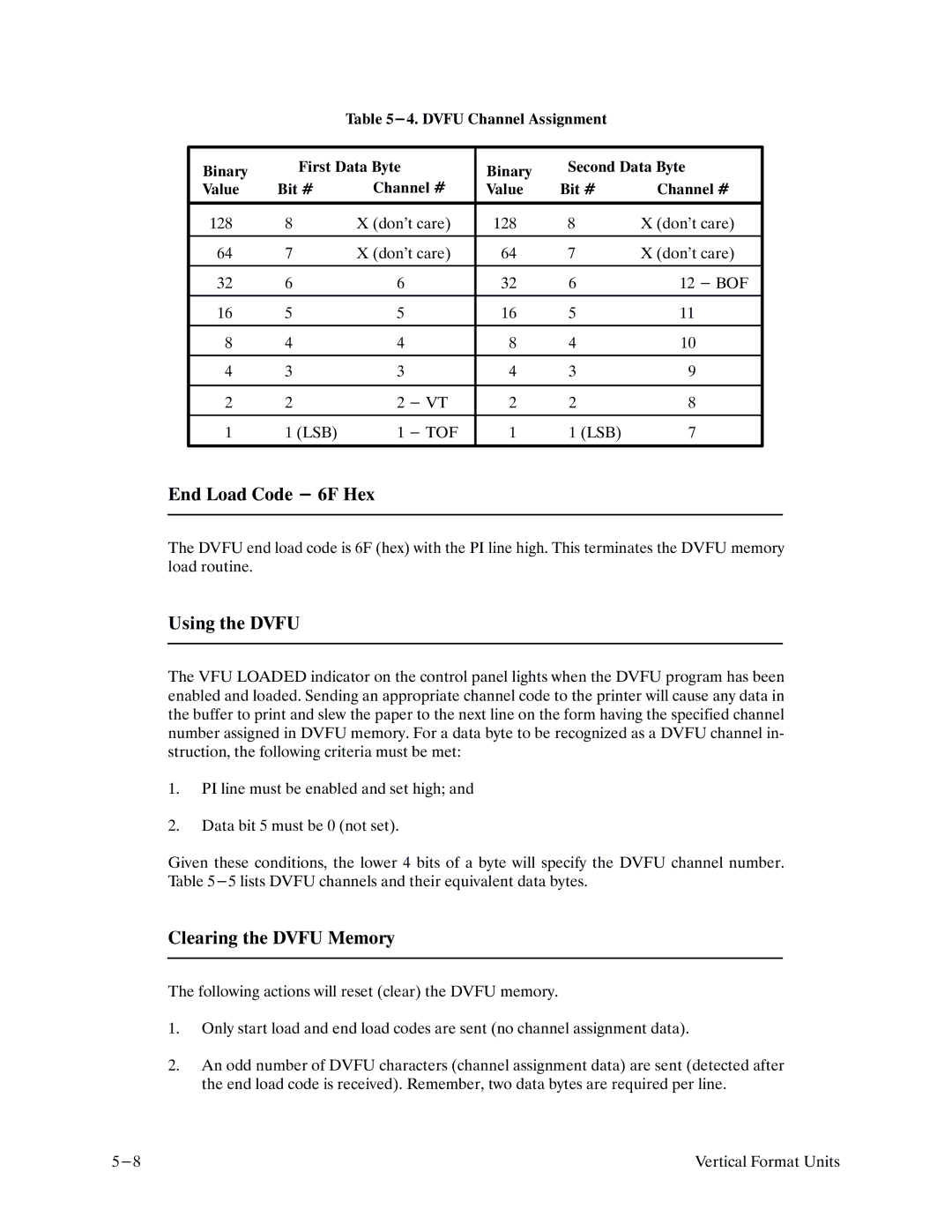
Table
Binary | First Data Byte |
| Binary | Second Data Byte | ||
|
|
|
|
| ||
Value | Bit # | Channel # | Value | Bit # | Channel # | |
|
|
|
|
|
| |
128 | 8 | X (don't care) | 128 | 8 | X (don't care) | |
|
|
|
|
|
| |
64 | 7 | X (don't care) | 64 | 7 | X (don't care) | |
|
|
|
|
|
|
|
32 | 6 | 6 |
| 32 | 6 | 12 - BOF |
|
|
|
|
|
|
|
16 | 5 | 5 |
| 16 | 5 | 11 |
|
|
|
|
|
|
|
8 | 4 | 4 |
| 8 | 4 | 10 |
|
|
|
|
|
|
|
4 | 3 | 3 |
| 4 | 3 | 9 |
|
|
|
|
|
|
|
2 | 2 | 2 | - VT | 2 | 2 | 8 |
|
|
|
|
|
|
|
1 | 1 (LSB) | 1 | - TOF | 1 | 1 (LSB) | 7 |
|
|
|
|
|
|
|
End Load Code - 6F Hex
The DVFU end load code is 6F (hex) with the PI line high. This terminates the DVFU memory load routine.
Using the DVFU
The VFU LOADED indicator on the control panel lights when the DVFU program has been enabled and loaded. Sending an appropriate channel code to the printer will cause any data in the buffer to print and slew the paper to the next line on the form having the specified channel number assigned in DVFU memory. For a data byte to be recognized as a DVFU channel inF struction, the following criteria must be met:
1.PI line must be enabled and set high; and
2.Data bit 5 must be 0 (not set).
Given these conditions, the lower 4 bits of a byte will specify the DVFU channel number. Table
Clearing the DVFU Memory
The following actions will reset (clear) the DVFU memory.
1.Only start load and end load codes are sent (no channel assignment data).
2.An odd number of DVFU characters (channel assignment data) are sent (detected after the end load code is received). Remember, two data bytes are required per line.
Vertical Format Units |
