maximum data line length (cable length) from the controller (host computer) to the printer is 40 feet.
Centronics Interface Signals
Table
Table
INPUT SIGNALS | OUTPUT SIGNALS | |||
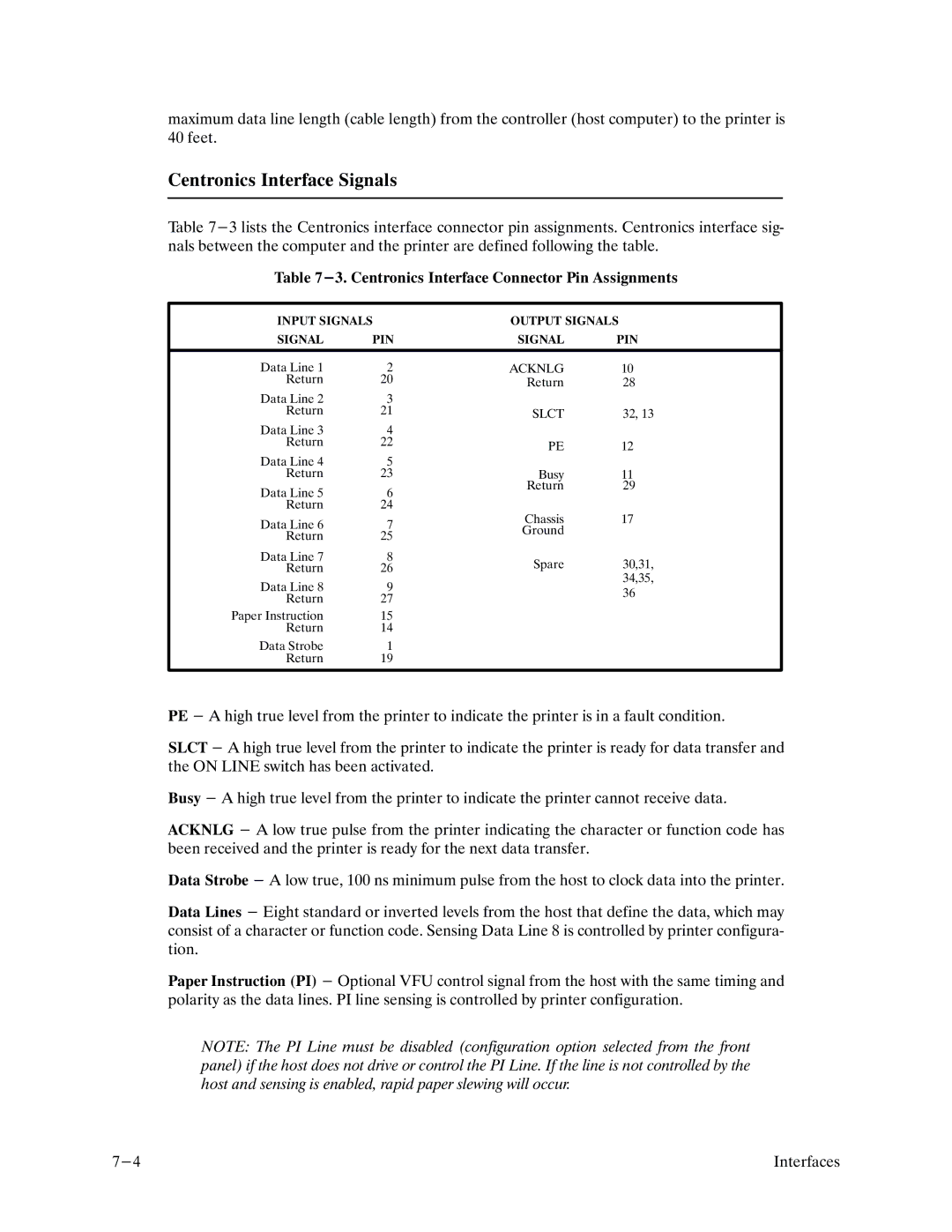
SIGNAL | PIN | SIGNAL | PIN | |
|
|
|
| |
Data Line 1 | 2 | ACKNLG | 10 | |
Return | 20 | Return | 28 | |
|
| |||
Data Line 2 | 3 |
|
| |
Return | 21 | SLCT | 32, 13 | |
|
| |||
Data Line 3 | 4 |
|
| |
Return | 22 | PE | 12 | |
|
| |||
Data Line 4 | 5 |
|
| |
Return | 23 | Busy | 11 | |
Data Line 5 | 6 | Return | 29 | |
|
| |||
Return | 24 |
|
| |
Data Line 6 | 7 | Chassis | 17 | |
Ground |
| |||
Return | 25 |
| ||
|
| |||
Data Line 7 | 8 | Spare | 30,31, | |
Return | 26 | |||
| 34,35, | |||
Data Line 8 | 9 |
| ||
| 36 | |||
Return | 27 |
| ||
|
| |||
Paper Instruction | 15 |
|
| |
Return | 14 |
|
| |
Data Strobe | 1 |
|
| |
Return | 19 |
|
| |
|
|
|
| |
PE - A high true level from the printer to indicate the printer is in a fault condition.
SLCT - A high true level from the printer to indicate the printer is ready for data transfer and the ON LINE switch has been activated.
Busy - A high true level from the printer to indicate the printer cannot receive data.
ACKNLG - A low true pulse from the printer indicating the character or function code has been received and the printer is ready for the next data transfer.
Data Strobe - A low true, 100 ns minimum pulse from the host to clock data into the printer.
Data Lines - Eight standard or inverted levels from the host that define the data, which may consist of a character or function code. Sensing Data Line 8 is controlled by printer configuraF tion.
Paper Instruction (PI) - Optional VFU control signal from the host with the same timing and polarity as the data lines. PI line sensing is controlled by printer configuration.
NOTE: The PI Line must be disabled (configuration option selected from the front panel) if the host does not drive or control the PI Line. If the line is not controlled by the host and sensing is enabled, rapid paper slewing will occur.
Interfaces |