1st BIT IMAGE DATA BYTE
2nd BIT IMAGE DATA BYTE
7th BIT IMAGE DATA BYTE
DECIMAL
WEIGHTS
128
64
32
16
8
4
2
1
|
|
|
|
|
|
|
|
|
|
|
|
73 |
| 36 |
| 36 |
| 73 | DECIMAL | ||||
|
|
|
|
|
|
|
|
|
|
| VALUES |
146 | 255 |
|
| 146 |
| ||||||
|
|
|
| ||||||||
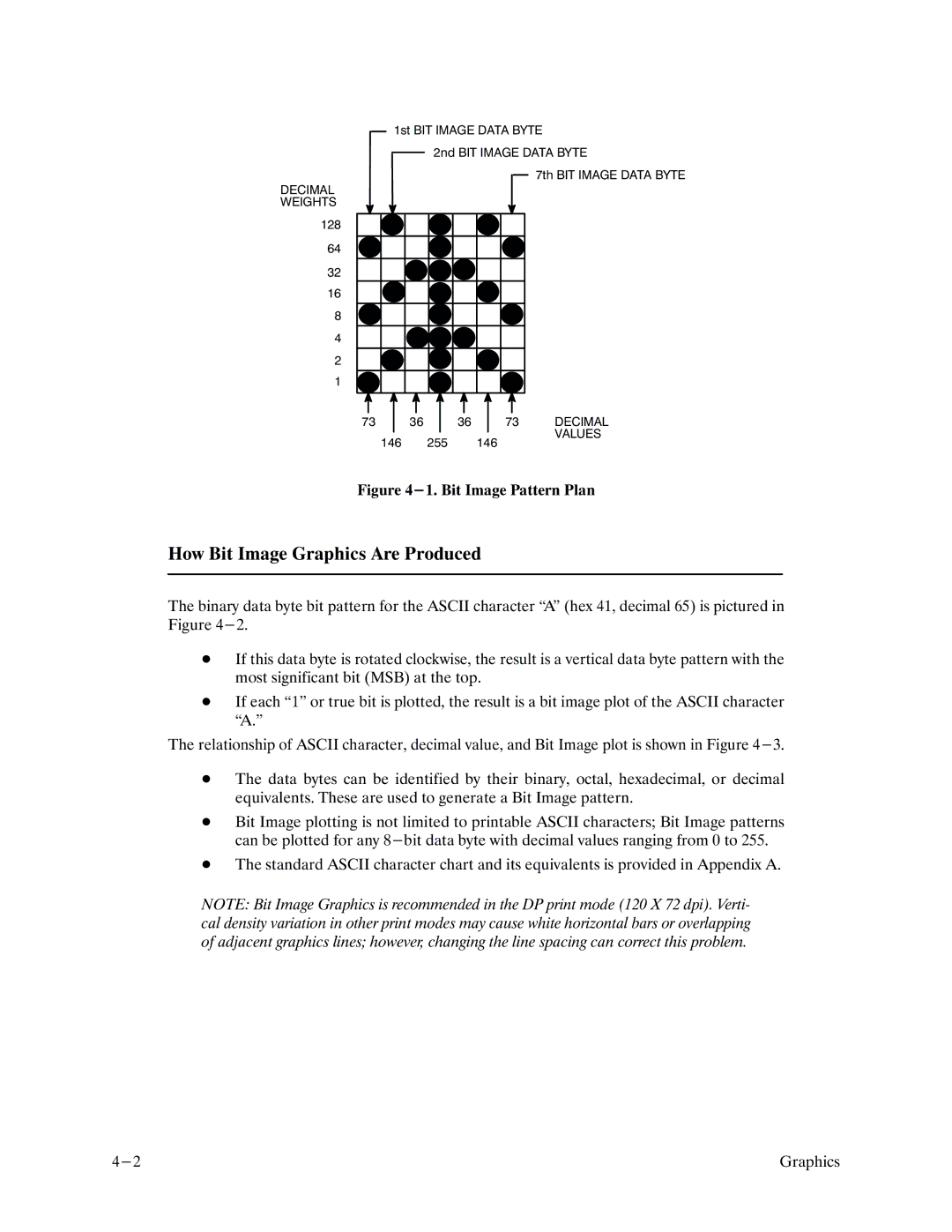
Figure 4-1. Bit Image Pattern Plan
How Bit Image Graphics Are Produced
The binary data byte bit pattern for the ASCII character •A" (hex 41, decimal 65) is pictured in Figure
DIf this data byte is rotated clockwise, the result is a vertical data byte pattern with the most significant bit (MSB) at the top.
DIf each •1" or true bit is plotted, the result is a bit image plot of the ASCII character •A."
The relationship of ASCII character, decimal value, and Bit Image plot is shown in Figure
DThe data bytes can be identified by their binary, octal, hexadecimal, or decimal equivalents. These are used to generate a Bit Image pattern.
DBit Image plotting is not limited to printable ASCII characters; Bit Image patterns can be plotted for any
DThe standard ASCII character chart and its equivalents is provided in Appendix A.
NOTE: Bit Image Graphics is recommended in the DP print mode (120 X 72 dpi). Verti/ cal density variation in other print modes may cause white horizontal bars or overlapping of adjacent graphics lines; however, changing the line spacing can correct this problem.
Graphics |