150, 300, 600, 1200, 2400, 4800, 9600, 19200, or external control are available. Baud rates are selected from the control panel; external control is selected by jumper configuration on the DCU board as described in Appendix F, Hardware Jumper Configuration.
The input format consists of a single start bit, 7 or 8 data bits, and one or two stop bits. The operator can set the number of data bits from the control panel. The data bits are interpreted with the least significant bit first. The operator can also set parity checking via control panel. The printer interface uses a
RS-232 Interface Signals
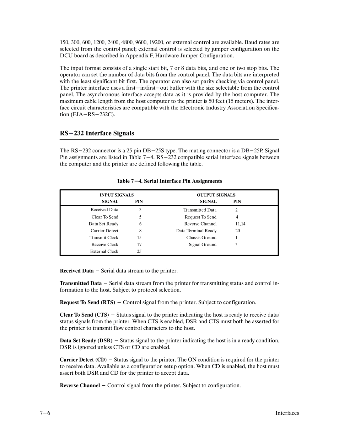
The
Table
INPUT SIGNALS |
| OUTPUT SIGNALS | |
SIGNAL | PIN | SIGNAL | PIN |
|
|
|
|
Received Data | 3 | Transmitted Data | 2 |
Clear To Send | 5 | Request To Send | 4 |
Data Set Ready | 6 | Reverse Channel | 11,14 |
Carrier Detect | 8 | Data Terminal Ready | 20 |
Transmit Clock | 15 | Chassis Ground | 1 |
Receive Clock | 17 | Signal Ground | 7 |
External Clock | 25 |
|
|
|
|
|
|
Received Data - Serial data stream to the printer.
Transmitted Data - Serial data stream from the printer for transmitting status and control inF formation to the host. Subject to protocol selection.
Request To Send (RTS) - Control signal from the printer. Subject to configuration.
Clear To Send (CTS) - Status signal to the printer indicating the host is ready to receive data/ status signals from the printer. When CTS is enabled, DSR and CTS must both be asserted for the printer to transmit flow control characters to the host.
Data Set Ready (DSR) - Status signal to the printer indicating the host is in a ready condition. DSR is ignored unless CTS or CD are enabled.
Carrier Detect (CD) - Status signal to the printer. The ON condition is required for the printer to receive data. Available as a configuration setup option. When CD is enabled, the host must assert both DSR and CD for the printer to accept data.
Reverse Channel - Control signal from the printer. Subject to configuration.
Interfaces |
