Page 21 |
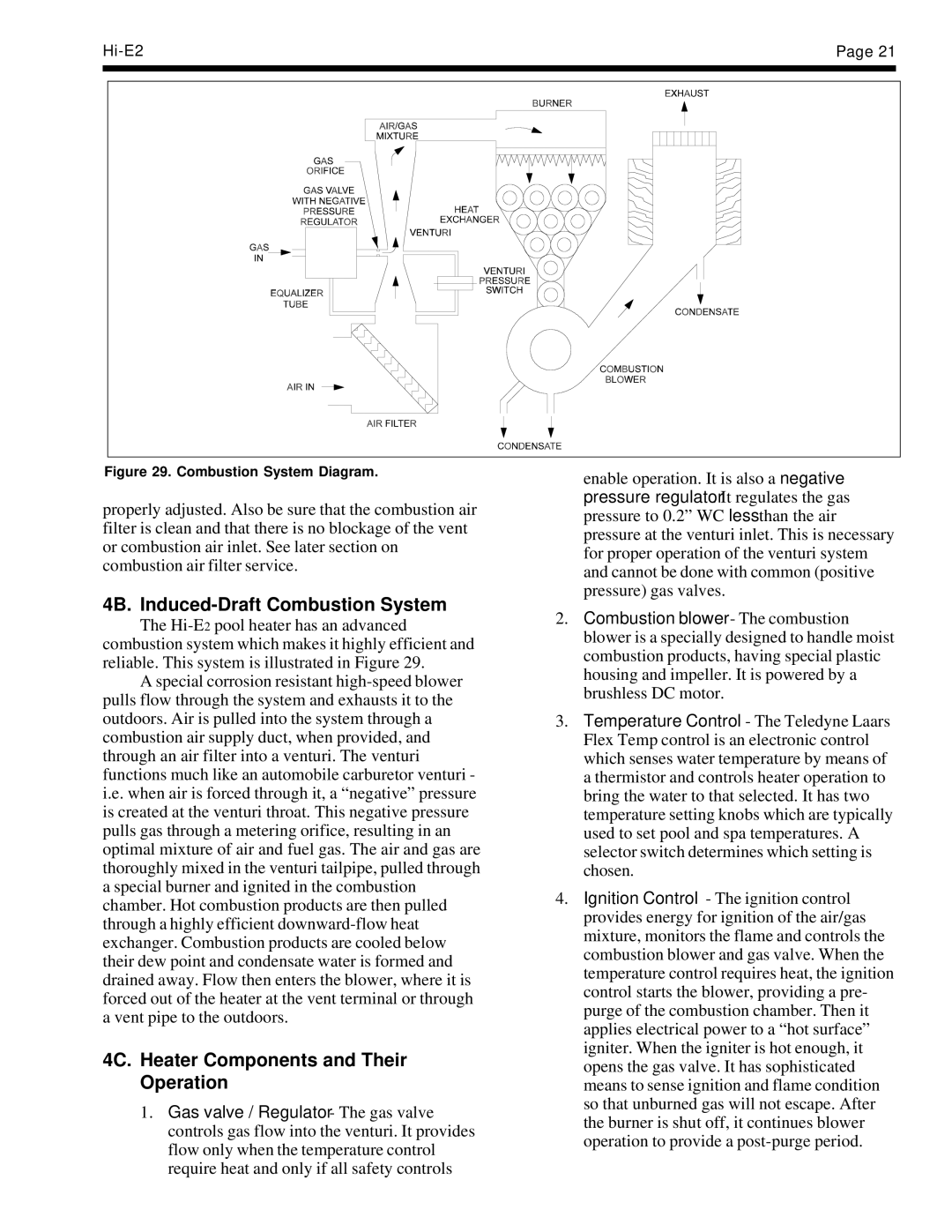
Figure 29. Combustion System Diagram.
properly adjusted. Also be sure that the combustion air filter is clean and that there is no blockage of the vent or combustion air inlet. See later section on combustion air filter service.
4B. Induced-Draft Combustion System
The
Aspecial corrosion resistant
4C. Heater Components and Their Operation
1.Gas valve / Regulator - The gas valve controls gas flow into the venturi. It provides flow only when the temperature control require heat and only if all safety controls
enable operation. It is also a negative pressure regulator. It regulates the gas pressure to 0.2” WC less than the air pressure at the venturi inlet. This is necessary for proper operation of the venturi system and cannot be done with common (positive pressure) gas valves.
2.Combustion blower - The combustion blower is a specially designed to handle moist combustion products, having special plastic housing and impeller. It is powered by a brushless DC motor.
3.Temperature Control - The Teledyne Laars Flex Temp control is an electronic control which senses water temperature by means of a thermistor and controls heater operation to bring the water to that selected. It has two temperature setting knobs which are typically used to set pool and spa temperatures. A selector switch determines which setting is chosen.
4.Ignition Control - The ignition control provides energy for ignition of the air/gas mixture, monitors the flame and controls the combustion blower and gas valve. When the temperature control requires heat, the ignition control starts the blower, providing a pre- purge of the combustion chamber. Then it applies electrical power to a “hot surface” igniter. When the igniter is hot enough, it opens the gas valve. It has sophisticated means to sense ignition and flame condition so that unburned gas will not escape. After the burner is shut off, it continues blower operation to provide a