Page 2
2B. Heater Assembly and Preparation
The
It is best to handle these preparations before the heater is in its final location. Instructions are provided in subsequent sections of this document.
Installation at High Elevation
The
2C. Heater Location
The
Install the heater at least 5 feet (1.52 meters) from the inside wall of the pool or spa unless the heater is separated from the pool or spa by a
When pool equipment is located below the pool surface, a leak from any component can cause large scale water loss or flooding. Teledyne Laars cannot be responsible for such water loss or flooding or resulting damage. Location of the heater below or above the pool deck affects operation of its water pressure switch. See sections on water piping and heater start- up for more information about this.
WARNING
When pool equipment is located below the pool surface, a leak from any component can cause large scale water loss or flooding. Teledyne Laars cannot be responsible for such water loss or flooding or resulting damage.
Locate the heater in an area where water leakage will not result in damage to the area around the appliance or to a structure. If forced to locate the heater where water leakage may cause damage, provide a suitable pan with drain under the heater. This pan must not restrict air flow or heater functions.
In selection of a location, disposal of combustion condensate must also be considered. The heater can produce three gallons of condensate water per hour under some operating conditions. Means to drain this condensate must be available or special provisions, such as a condensate pump must be provided. See later section on condensate disposal.
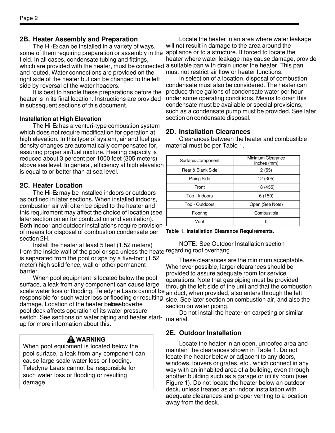
2D. Installation Clearances
Clearances between the heater and combustible material must be per Table 1.
Surface/Component | Minimum Clearance | ||
Inches (mm) | |||
| |||
Rear & Blank Side | 2 | (55) | |
|
|
| |
Piping Side | 12 | (305) | |
|
|
| |
Front | 18 | (455) | |
|
| ||
Top - Indoors | 6 (150) | ||
|
| ||
Top - Outdoors | Open (See Note) | ||
|
| ||
Flooring | Combustible | ||
|
|
| |
Vent |
| 0 | |
|
|
| |
Table 1. Installation Clearance Requirements.
NOTE: See Outdoor Installation section regarding roof overhang.
These clearances are the minimum acceptable. Whenever possible, larger clearances should be provided to assure adequate room for service operations. Note that gas piping must be provided through the left side of the unit and that the combustion air duct, when provided, also enters through the left side. See later section on combustion air, and also the section on water piping.
Do not install the heater on carpeting or similar material.
2E. Outdoor Installation
Locate the heater in an open, unroofed area and maintain the clearances shown in Table 1. Do not locate the heater below or adjacent to any doors, windows, louvers or grates, etc., which connect in any way with an inhabited area of a building, even through another building such as a garage or utility room (see Figure 1). Do not locate the heater below an outdoor deck, unless treated as an indoor installation with adequate clearances and proper venting to a location away from the deck.