| Page 27 | |
+ | - | - |
| + |
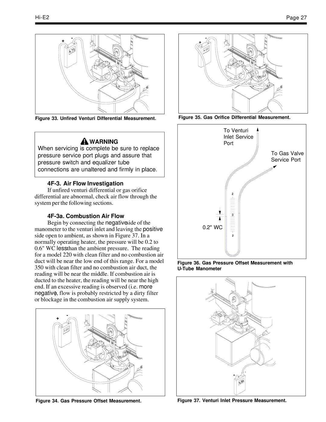
Figure 33. Unfired Venturi Differential Measurement. | Figure 35. Gas Orifice Differential Measurement. |
![]() WARNING
WARNING
When servicing is complete be sure to replace pressure service port plugs and assure that pressure switch and equalizer tube connections are unaltered and firmly in place.
4F-3. Air Flow Investigation
If unfired venturi differential or gas orifice differential are abnormal, check air flow through the system per the following sections.
4F-3a. Combustion Air Flow
Begin by connecting the negative side of the manometer to the venturi inlet and leaving the positive side open to ambient, as shown in Figure 37. In a normally operating heater, the pressure will be 0.2 to 0.6" WC less than the ambient pressure. The reading for a model 220 with clean filter and no combustion air duct will be near the low end of this range. For a model 350 with clean filter and no combustion air duct, the reading will be near the middle. If combustion air is ducted to the heater, the reading will be near the high end. If an excessive reading is observed (i.e. more negative), flow is probably restricted by a dirty filter or blockage in the combustion air supply system.
+ | - |
|
To Venturi
Inlet Service
Port
To Gas Valve
Service Port
0.2" WC
Figure 36. Gas Pressure Offset Measurement with U-Tube Manometer
Figure 34. Gas Pressure Offset Measurement. | Figure 37. Venturi Inlet Pressure Measurement. |