Page 28
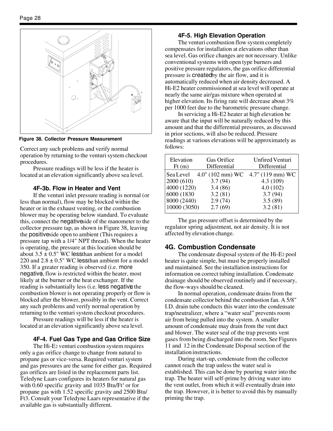
Figure 38. Collector Pressure Measurement
Correct any such problems and verify normal operation by returning to the venturi system checkout procedures.
Pressure readings will be less if the heater is located at an elevation significantly above sea level.
4F-3b. Flow in Heater and Vent
If the venturi inlet pressure reading is normal (or less than normal), flow may be blocked within the heater or in the exhaust venting, or the combustion blower may be operating below standard. To evaluate this, connect the negative side of the manometer to the collector pressure tap, as shown in Figure 38, leaving the positive side open to ambient (This requires a pressure tap with a 1/4" NPT thread). When the heater is operating, the pressure at this location should be about 3.5 ± 0.5" WC less than ambient for a model 220 and 2.8 ± 0.5" WC less than ambient for a model
350.If a greater reading is observed (i.e. more negative), flow is restricted within the heater, most likely at the burner or the heat exchanger. If the reading is substantially less (i.e. less negative), the combustion blower is not operating properly or flow is blocked after the blower, possibly in the vent. Correct any such problems and verify normal operation by returning to the venturi system checkout procedures.
Pressure readings will be less if the heater is located at an elevation significantly above sea level.
4F-4. Fuel Gas Type and Gas Orifice Size
The
4F-5. High Elevation Operation
The venturi combustion flow system completely compensates for installation at elevations other than sea level. Gas orifice changes are not necessary. Unlike conventional systems with open type burners and positive pressure regulators, the gas orifice differential pressure is created by the air flow, and it is automatically reduced when air density decreased. A
In servicing a
Elevation | Gas Orifice | Unfired Venturi | |
Ft (m) | Differential | Differential | |
Sea Level 4.0" (102 mm) WC | 4.7" (119 mm) WC | ||
2000 | (610) | 3.7 (94) | 4.3 (109) |
4000 | (1220) | 3.4 (86) | 4.0 (102) |
6000 (1830 | 3.2 (81) | 3.7 (94) | |
8000 | (2440) | 2.9 (74) | 3.5 (89) |
10000 (3050) | 2.7 (69) | 3.2 (81) | |
|
|
|
|
The gas pressure offset is determined by the regulator spring adjustment, not air density. It is not affected by elevation change.
4G. Combustion Condensate
The condensate disposal system of the
In normal operation, condensate drains from the condensate collector behind the combustion fan. A 5/8" I.D. drain tube conducts this water into the condensate trap/neutralizer, where a “water seal” prevents room air from being pulled into the system. A smaller amount of condensate may drain from the vent duct and blower. The water seal of the trap prevents vent gases from being discharged into the room. See Figures 11 and 12 in the Condensate Disposal section of the installation instructions.
During